What gauge cable?

How to fix gremlins & general maintenance issues ...
User avatar
Silverbullet
Senior Member
Posts: 2865
Joined: Mon Aug 23, 2010 6:20 pm
Location: Adelaide

What gauge cable?

Post by Silverbullet » Sat Aug 01, 2015 5:44 pm

So it's decided I am re-wiring my wagon myself. The more I look at what is involved the more I see it shouldn't be that complicated for such a simple car. I've got 2 different FSMs to look at with wiring diagrams for almost every circuit, plus this way I can add improvements where I see fit and end up with exactly what I want. I'm thinking all LED tail lights among other things :) At this stage I have a good idea on how I'm going to power everything; I'm having a more modern fuse box in the engine bay next to the battery with relays built in, and ditching the fusible links for modern circuit breakers.

I've got a fuse box from an early Liberty which should fit my purposes. It has 6 relays and enough fuse positions in there for everything, if not I plan to maybe put in a smaller sub-fuse box say under the dash in the stock location with its power feed from a relay in the engine bay. This might power things like the interior and map lights, CB radio, sound system, dash lights and also a source of power to run through the factory switches out to the relays in the engine bay for things like headlights.

Problem is you can't just walk into a store and buy automotive cable by the meter in 10 different colors and 3 different gauges. So online is the option I'm going with, and also salvaging stuff from the old loom. So my main question is what gauge cable do I use? There's alot of conflicting information on the web. On the Lib fuse box it seems the single main power feed from the battery is around 6mm, 2 or 3 AWG, good for around 150 Amps according to some charts, but the website I'm buying from says their 6mm is only good for 50 amps??

All the other higher powered fuses in there (50 amps) seem to have 4 or 5mm just going by the outside diameter of the cable. For the cable to the starter, I've heard 1 AWG is required.

So would my under-dash sub fuse box need as much as 3 AWG to feed it or could I go with something smaller?

That's a big enough wall of text for now :( I was hoping I could order some cable this weekend, but there's too much conflicting information around I would probably end up with 20 meters of the wrong stuff :evil: And not being able to just go out and buy what I need when I need it is really annoying, have to order a lot of stuff at once to make the postage worth it.
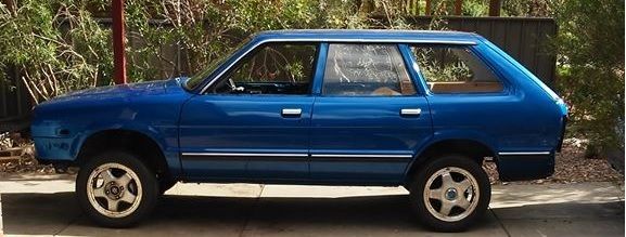
Will it ever end!?
-EA81 TWIN CARB!!!!
-L series 5 speed
-Custom paint job
-2" lift
-Full custom re-wire
-L series front end
Image

User avatar
tambox
Junior Member
Posts: 661
Joined: Tue Sep 09, 2008 5:06 pm
Location: Clayton again

Post by tambox » Sat Aug 01, 2015 9:26 pm

When you look at cables, the rating of the cable is current vs voltage drop over length. Theoretically heat wont be involved as your cable ratings will exceed your requirements.

To do it by the book you need to know how much current is drawn by that device, vs how much voltage it needs to operate correctly. When you know the length of the cable, you can work out the core size required.

Then you get into strand sizes/types (tinned/bare), that's why similar core sizes can carry different currents.
Also insulation thickness and types.

Sorry for not simplifying it, but OEM get cables made to suit what they need and meet the standards required for safe use in a vehicle.

Its not a simple task you are taking on.
Wire's ain't wire's.

It usually works out easier to use OEM loom and add your extra's to it.
L serious, still.

User avatar
Silverbullet
Senior Member
Posts: 2865
Joined: Mon Aug 23, 2010 6:20 pm
Location: Adelaide

Post by Silverbullet » Sat Aug 01, 2015 11:25 pm

Thanks for the advice tambox, I did have some inkling about the wattage of certain devices and how long the cable was determining the conductor size. In the FSMs I have there is a listed wattage for any given electrical component. Even better than that I have just learned in the whole car wiring diagram there is a code at each end of any wire e.g "1.25 BW" which tells you the diameter of the conductor for that wire and its color. In the table its saying 1.25 has a conductor of 1.5mm diameter with an allowable current of 19 amps, BW meaning black with a white stripe :) That is for one of the power wires to the rear wiper motor :cool:

So that is a help for determining what I need. The parts I was struggling with was the non-factory stuff I am planning to make. But then there is quite a limited size range of wire you can get (in Aus anyway) I have found a different site that sells 3, 4, 5 and 6mm wire, then a different category of thinner stuff for sensors and instruments and 6 sizes of heavy stuff e.g battery cables and starter cables, all made in Australia :cool:
Will it ever end!?
-EA81 TWIN CARB!!!!
-L series 5 speed
-Custom paint job
-2" lift
-Full custom re-wire
-L series front end
Image

User avatar
steptoe
Master Member
Posts: 11582
Joined: Thu Oct 06, 2005 10:00 am
Location: 14 miles outside Gotham City

Post by steptoe » Sun Aug 02, 2015 9:22 am

Not attempting the CAN BUS stuff then :p and from my understaing this is where wire runs from front to back of vehicle is limited to a power wire, maybe an earth wire and a signal wire from a front computer to slave computer up the back to switch power to everything up the back end. If that is not CAN BUS summed up correctly, I am wrong and up some garden path ......

I am wondering if you are going to drive this baby when finished or will it be too precious ?

Great work so far anyway Sam

User avatar
Subydoug
Junior Member
Posts: 988
Joined: Wed Feb 08, 2012 10:19 pm
Location: Carlisle WA

Post by Subydoug » Sun Aug 02, 2015 10:42 am

Sam, a few things I remember from when I did mine. Headlights draw about 4 amps each, interior cabin fan was pretty hungry, around the 7amp mark, thermo fan (white one in metal shroud) is pretty greedy, cant say Ive measured it but its probably around the 8-10amp mark. fuel pump, couple amps, indicators, couple amps, coil 2-3amps......cant think of any other things in a standard MY that will be very current hungry.

I used around 18awg for most things, mainly because I had a roll of it. I think the tail lights were thinner gauge and if you go to LED's you wont need much power running back there at all (unless you use a trailer plug). Nothing draws much power in these cars, it is only a 50amp alternator after all.

FYI you can also use late model alternators in your car, Im using a Foz 80amp unit. just needs a different plug. Bolts straight in and the standard MY pulley will fit straight on but for bonus points if you machine 2mm off of the shaft bush it aligns the belt perfectly. One of the best upgrades Ive done to my car.

Regards

Doug

User avatar
Silverbullet
Senior Member
Posts: 2865
Joined: Mon Aug 23, 2010 6:20 pm
Location: Adelaide

Post by Silverbullet » Sun Aug 02, 2015 12:28 pm

I did think about CAN-bus or something similar for this car, it certainly made alot of sense regarding wiring; you pretty much have one USB cable running around the entire car with 1 main brain talking to several other slave computers which then tell the various appliances what to do. You can daisy chain things together and add bits in wherever you want but it still only has 1 data cable. I decided not to in the end either because you can't buy the computers to do it yourself (or were ridiculously expensive) or the ones you can buy (arduino based usually) are not really designed to last in hostile environments like engine bays and car rear quarter panels. And Yes Jonno this car will be driven and enjoyed :)

Thanks Doug that info is very helpful re power consumption that you observed. I figured the interior fan would suck the most power out of anything inside the cabin, with headlights and rad fan(s) being the other power hungry parts apart from the starter. If you measured only 4amps per headlight that does surprise me. I was "budgeting" for 20 amps :eek: So what I have planned should be more than enough. And yes I plan to put a bigger alternator on there too :)

I went ahead and ordered a load of wire of varying sizes and colors. I erred on the side of caution (20 amp headlights :rolleyes:) so I think I will be safe with what I've ordered. The website I went with is here Mostly Aussie made and very reasonably priced. Gets good reviews for speed and service as well. Only other thing I need is terminals, going with self sealing heat-shrink type and I'll buy the bigger multi pin connectors when I know what I need. Maybe waterproof/Deutsch connectors? :p
Will it ever end!?
-EA81 TWIN CARB!!!!
-L series 5 speed
-Custom paint job
-2" lift
-Full custom re-wire
-L series front end
Image

User avatar
Subydoug
Junior Member
Posts: 988
Joined: Wed Feb 08, 2012 10:19 pm
Location: Carlisle WA

Post by Subydoug » Sun Aug 02, 2015 1:13 pm

4 amps per light, so for a quad headlight like mine thats 8 amps lo beam and 16amps high beam. It depends on how you wire it to what gauge you need. You can wire it up with all the lights having separate power and GND feeds, or you can do what I did and run a heavier wire down to the drivers light, then jump from that light to the next with a lower gauge wire.

Stock headlights are a shade brighter then candles, 4 amps at 12v is ~50W per light. Highly recommend the updated alternator. Mine was crapping out when the thermo fans kicked in and the headlights were on at idle. I have a bit of extra load now being EFI.

Regards

Doug

User avatar
Silverbullet
Senior Member
Posts: 2865
Joined: Mon Aug 23, 2010 6:20 pm
Location: Adelaide

Post by Silverbullet » Sun Aug 02, 2015 1:52 pm

I have single headlights only so my 20A circuit plan should be sufficient? I'm also ditching the original sealed beams in favor of something like this with their "H4 standard" 55/60w" bulbs. The relays will be in the fuse box and the ones that were in there seem to be 20A anyway. Is there any benefit to either system of wiring the headlights? 2 wires or 1 wire and jumping it across.
Will it ever end!?
-EA81 TWIN CARB!!!!
-L series 5 speed
-Custom paint job
-2" lift
-Full custom re-wire
-L series front end
Image

User avatar
Subydoug
Junior Member
Posts: 988
Joined: Wed Feb 08, 2012 10:19 pm
Location: Carlisle WA

Post by Subydoug » Mon Aug 03, 2015 8:24 pm

Up to you really. I think the "proper" way is to run individual power feeds to each light but in the case of our subarus the voltage drop from jumping from one lamp to the next will be unnoticeable.

I did some measurements today with the clamp meter at work. My car draws about 10amps at idle with the engine running and a few misc things on in the car like the radio and the cabin lamp. In my case about 6 of that was running fuel pumps. In a carby car you can call that 2amps and be pretty safe. Im also running injectors. Bit harder to measure them as It changes with engine load and such but Id guess its safe to say they are probably only contributing an amp or so. That gets a standard MY base current down to around the 5amp mark.

Interior fan, I was a little bit off, it pulled ~8.5amps on full speed. Headlights I was also a bit off. I think when I checked them years back I used my bench supply at 12v. With 14v pumping into them they draw a combined of around 11amps. Hi beam in your case will be very similar because your not running the extra two globes.

I would measure the therm fan but my non-factory one is hard-wired in to the factory one so I cant really tell how much it draws by itself. Indicators are pretty greedy, hazards gave about 7amps when they all lit up! Probably not concern you as your talking about LED's. I didnt get a chance to measure anything else but Let me know and Il see what I can do the measure it.

Regards

Doug

User avatar
Silverbullet
Senior Member
Posts: 2865
Joined: Mon Aug 23, 2010 6:20 pm
Location: Adelaide

Post by Silverbullet » Mon Aug 03, 2015 10:35 pm

That's all helpful, thanks again :) With all the cable I've ordered I don't think I'll be burning any wires out; the smallest automotive cable in the Rapid cables store was "3mm" and they rated that at 20 amps capable. Apart from their "ultra thin" for running things like instruments and dash lights, sensors and signal wires to relays which I got plenty of as well.

The things I would be most interested in are all the interior accessories combined but of course that varies from car to car. That would just be to see if 4 power windows going up with all the interior and map lights on, radio up full blast, CB blaring and A/C on full blast...would that blow a 50A fuse? :eek:
Will it ever end!?
-EA81 TWIN CARB!!!!
-L series 5 speed
-Custom paint job
-2" lift
-Full custom re-wire
-L series front end
Image

User avatar
Subydoug
Junior Member
Posts: 988
Joined: Wed Feb 08, 2012 10:19 pm
Location: Carlisle WA

Post by Subydoug » Tue Aug 04, 2015 8:38 am

I dont have ac.....but I can try the rest.

Regards

Doug

User avatar
legacytt
Junior Member
Posts: 215
Joined: Thu Oct 06, 2005 10:00 am
Location: Launceston,Tas

Wiring

Post by legacytt » Tue Aug 04, 2015 5:43 pm

Are you going to be running an EJ? If so why not use a complete Liberty Loom front and rear and adapt your MY Dash to suit it. Much easier than a full rewire.
Gen 1 Legacy GT 3inch lift and 28's

User avatar
Subydoug
Junior Member
Posts: 988
Joined: Wed Feb 08, 2012 10:19 pm
Location: Carlisle WA

Post by Subydoug » Tue Aug 04, 2015 8:03 pm

Legacytt, pretty sure Silverbullet plans on the standard motor with twin carbies. He's the best one to answer that though.

Measured the windows today, only 7.5amps all going up. Mine dont seem to struggle too bad and are factory. I dont know what the aftermarket ones you installed will draw, you need to test that one yourself. Besides, windows only take a few seconds to wind down and up so they are the least of your worries as far as cable gauge and alternator draw go.

I re-read your previous post, 40amps should do but it depends on how you go about your breakers. Personally I would have individual breakers for BATT, ACC and IGN circuits. Couple of reasons, you can isolate them individually if wanted and if there is a fault you will have a pretty good ball park where to look. That being the case it then depends on what you want wired to which key position. Mostly personal preference so Il let you use your noodle on that one.

Regards

Doug

User avatar
Silverbullet
Senior Member
Posts: 2865
Joined: Mon Aug 23, 2010 6:20 pm
Location: Adelaide

Post by Silverbullet » Tue Aug 04, 2015 9:29 pm

Legacytt: No EJ in this beastie :) EA81 twin carb motor which would have been fine to use the original wiring but I'm also converting to 6 gauge instrumentation, which I got from NZ and the wiring that came with it is completely in-compatible with my very early AUDM MY wiring. Come to think of it I can't remember seeing another MY wagon or ute with glass tube fuses under the dash, they've all been blades.

Doug, the fuse box I bought out of the Lib has I think 3 x 45-50A cartridge type fuses in it, for things like ABS (or so it says on the box lid) but I'm struggling to think of anything I'll have that needs a 50A circuit. So I thought I could just use one of them to run the entire interior via a smaller sub-fuse box under the dash. As for ACC and IGN circuits, haven't decided whats what in that department yet.

Here's a question; how can I wire X number of circuits to the IGN only position? If I don't want all the power running through the key barrel. I originally thought a big beefy relay under bonnet but all these relays for this and that, they're gonna start piling up :eek:
Will it ever end!?
-EA81 TWIN CARB!!!!
-L series 5 speed
-Custom paint job
-2" lift
-Full custom re-wire
-L series front end
Image

User avatar
Bantum
General Member
Posts: 1923
Joined: Sun Jul 29, 2012 4:30 pm
Location: Northern Territory + QLD
Contact:

Master ...

Post by Bantum » Wed Aug 05, 2015 12:55 am

Like what your attempting to do, keep at it make sure you post up some pics of your work too !

Re: Wire gauges - I'd just go with what was there originally, just remember to label everything for future reference ... ;)

Liking your idea of having a master relay - I'd locate it next to fuse box & run it of the 'acc' from ignition key - with power direct from battery via relay to the fuse box.

P.S. - I'm also working on a wiring diagram for my '82 touring wagon, will post it up in the 'download' section for reference in the near future ... :)

These are screen shots of work in progress :

Image

The above was done ages ago & is incomplete, the aim is to update it with all the Relays, A/C etc. below :

Image

It's taking longer than I'd hoped with most complex bit being around the fuse box ... :rolleyes:

Cheers, Bantum ...

User avatar
tambox
Junior Member
Posts: 661
Joined: Tue Sep 09, 2008 5:06 pm
Location: Clayton again

Post by tambox » Wed Aug 05, 2015 7:30 am

Like Doug mentioned, separate circuits for the main feeds.
1 breaker/relay for ACC, 1 breaker/relay for IGN.
A distribution block after each relay.
Neat and simple.
That's the way I've been doing it.
L serious, still.

User avatar
Silverbullet
Senior Member
Posts: 2865
Joined: Mon Aug 23, 2010 6:20 pm
Location: Adelaide

Post by Silverbullet » Wed Aug 05, 2015 8:14 pm

Bantum, you da man! Those wiring diagrams are really nice, old and incomplete or not :) The multi colored lines make it so easy to follow compared to the ones in the FSM. Did you use any special program to draw those up? Something easier than MS paint I mean. Probably would be a good idea for me to do something similar, I've got AutoCAD on this PC that would probably do it.

Here's a very rough and very un-detailed sketch of the plan I have in my head (not a patch on Bantums I know but it is very rough ;))

Can anyone see any potential problems with this?
Attachments
draft.jpg
draft.jpg (93.93 KiB) Viewed 4497 times
Will it ever end!?
-EA81 TWIN CARB!!!!
-L series 5 speed
-Custom paint job
-2" lift
-Full custom re-wire
-L series front end
Image

User avatar
tambox
Junior Member
Posts: 661
Joined: Tue Sep 09, 2008 5:06 pm
Location: Clayton again

Post by tambox » Wed Aug 05, 2015 9:12 pm

Just have to be careful with the always on circuit.
Why the relay? (race car kill switch :) )
It will always draw power = potential flat bat.
Always on should only be a minor current (ma), a small fuse from before the ACC relay or similar would do.
L serious, still.

User avatar
Bantum
General Member
Posts: 1923
Joined: Sun Jul 29, 2012 4:30 pm
Location: Northern Territory + QLD
Contact:

Cad up ...

Post by Bantum » Thu Aug 06, 2015 12:27 am

Yep - All done in Autocad, if you can hang on for a bit I will post up a *.pdf of the finished project - or if you really want I can send you the file, just don't expect it for some time yet as I've got to finish it first ... :)

You probably don't need 100 amp fuses, as it would do more damage than protection - better off going for something similar to the original. From memory, your standard Brumby fusible links were something like 40, 60 & 80 amp ( there's a whole discussion thread about them on here somewhere ) also I believe they already have a built-in allowance of 2 to 3% ? over max current draw.

If you going for re-settable fuses, might need to check what sort you can get. I would also need to see what fuses / wires are going where to make full sense of that mud map, but your sort of on the right track ... ;)

Maybe do a breakout diagram of each box showing what wires go where etc. using your reference diagrams as examples of how to draw 'em up, that way you'd get a better understanding of what goes where.

Keep at it - I'm still learn'n after many years of tinkering ... :)

Cheers, Bantum ...

User avatar
Silverbullet
Senior Member
Posts: 2865
Joined: Mon Aug 23, 2010 6:20 pm
Location: Adelaide

Post by Silverbullet » Thu Aug 06, 2015 6:37 pm

:D
Image

Wires and cables arrived today, hopefully it's enough :rolleyes: Now all I need is a suitable selection of crimp and heat shrink terminals. I highly recommend Rapid Cables to anyone looking for automotive cable, huge selection, mostly Aussie made and very well priced.

Bantum, did I say that diagram was rough? ;) Something I threw together in about 10 minutes last night to get across some sort of hint as to what I was planning. 100A does seem like alot, I only went with that and a (?) because in the FSM it says something like "if the fusible link wire melts within 10 seconds then there is approximately 150 amps draw through the wire" :shock: For circuit breakers I was thinking something like this
60-80 is good to know, I'll try and find that thread.

I will have to make a more detailed mud map with what accessory is going to which circuit (constant, ACC, or IGN) Something to do while I wait for some terminals. I also think I'm going to need more relays.
Will it ever end!?
-EA81 TWIN CARB!!!!
-L series 5 speed
-Custom paint job
-2" lift
-Full custom re-wire
-L series front end
Image

Post Reply

Return to “Electrical, Wiring and Lighting”