Today I've been fiddling around with Sunnie the brumby to get some electric window motors fitted. I have to give credit to SuBaRiNo Dave, with out dave helping me out I'd still be scratching my head...
Okay, what you need:
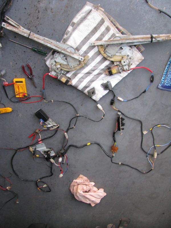
- MY electric window regulators, left and right. It doesn't appear to matter if they're front or back as the regulator design is the same, the window runner is different.
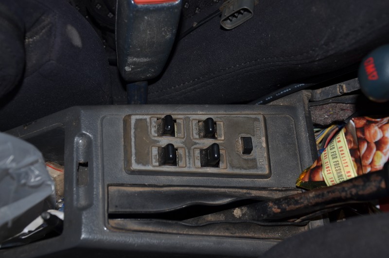
- Either a touring wagon electric window wiring loom, console and switches or
- A back yard wiring loom that looks like this:
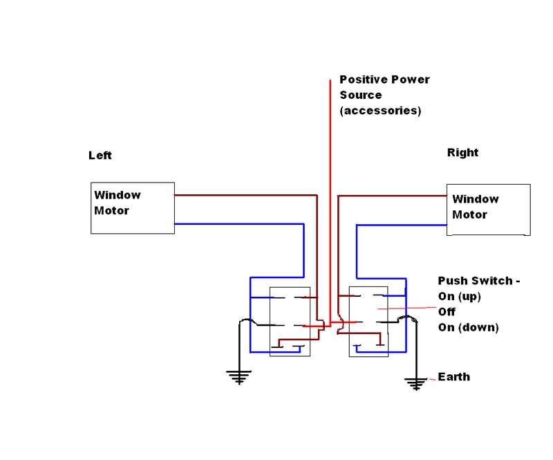
The switches need to be a push type ON OFF ON switch of about 20 Amps so I've been told. This was how I was going to do it originally.
But having got hold of a touring wagon loom I've used this and cut out a lot of work.
Now, the doors:
This is what your door looks like now without any trim mounted: Your looking at your window winder bolts. 4 for the regulator on the left, 2 for the secondary arm guide on the right:
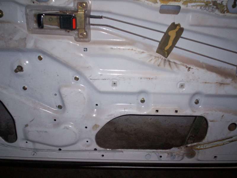
Remove the regulator from the door. You will need to have the window down to undo the bolts holding the window runner to the window. What you need to get off this is the window runner, then forget about the hand winder regulator:
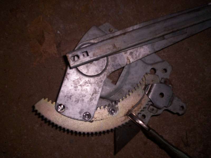
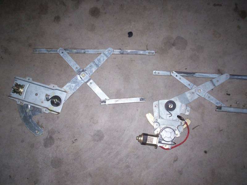
1) This is your hand winder regulator on the left and the touring wagon regulator on the right - roughly the way it mounts in the door:
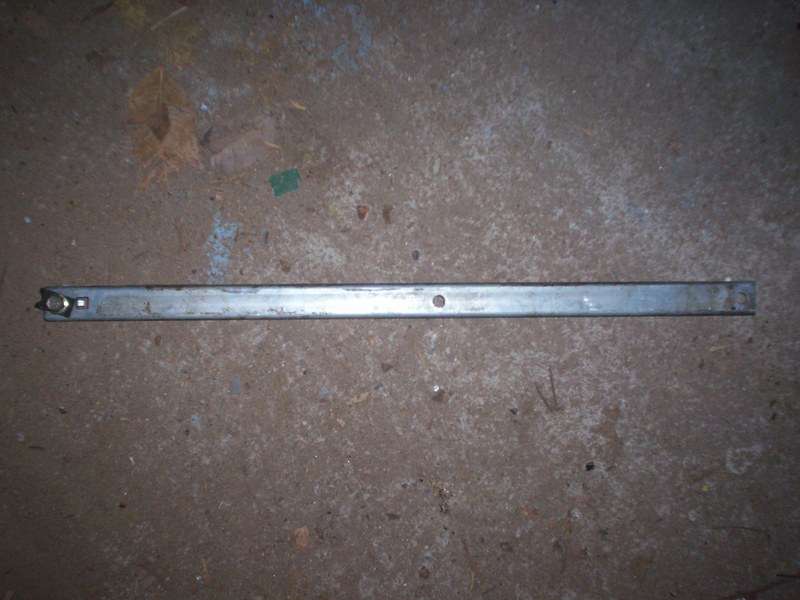
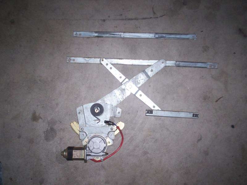
This is the change in the window runner, the touring wagon unit is above the electric motor regulator that is fitted with the brumby/coupe window runner:
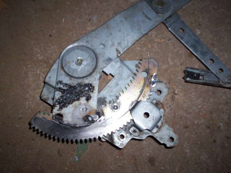
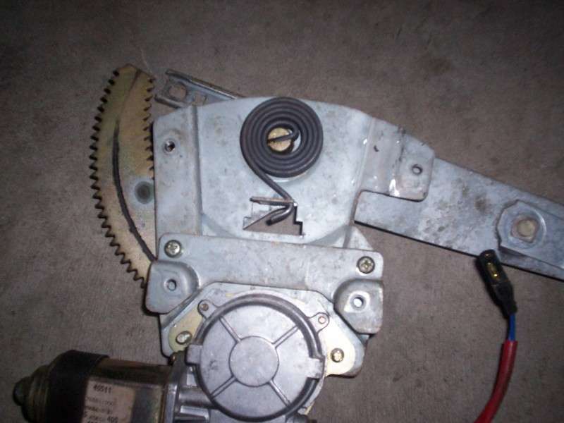
3 bolt mounts are high - the one that is not screwed to the unit needs to be flattened out, otherwise the unit won't fit. This is the pic showing the top right bolt hole flattened out - it was not used in the install in the car:
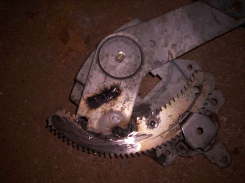
I don't have a pic of the bolts installed, but have indicated below which ones have been used, the cluster of three on the left are the motor and regulator, the two on the right are the secondary arm guide - You should beable to see the metal moulding for the fitment of the motor and regulator:
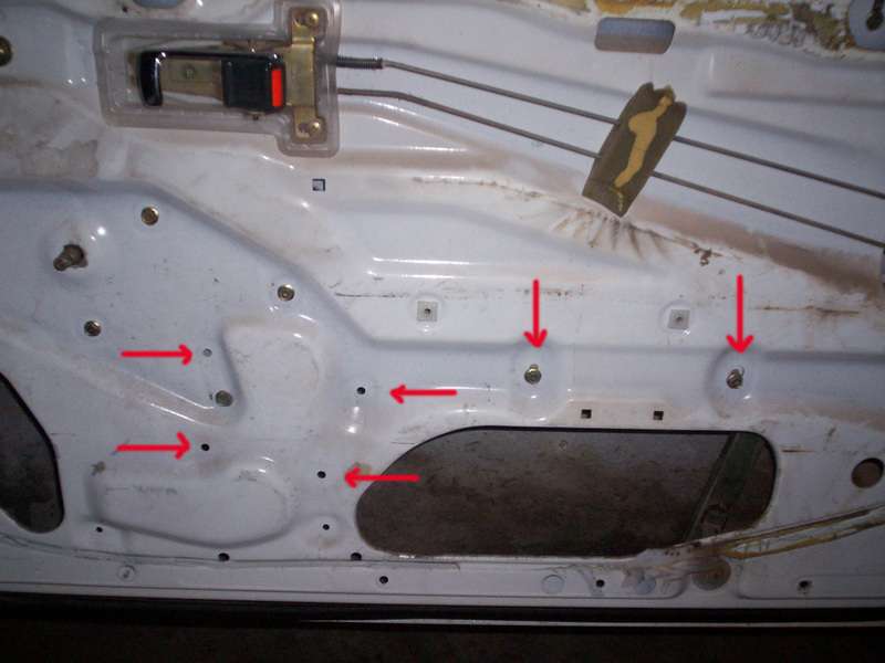
The horizontial arrows are the mounting holes for the regulator, the vertical arrows for the secondary arm guide. The top right hole will not be used, I'm not sure as to why I highlighted it.
Operation of window:
Well, it worked well, a slow period in the driver's door in the middle but it was steady. The window will not wind all the way down, there is 2 or 3 inches of the window left exposed when the motor has reached the end of the gear "sproket".
I'm not happy with this - tomorrow I will be modifying the electric window regulator - when the motor has the window as far up as it can go there is still about 3 inches of usable sproket that the motor cannot utilise. My aim is to pin the sprocket to the regulator framework, drill out the spot welds and slide the arm along further before re-welding it to the sproket.
Wait out for pics and further write up before posting please.
Cheers
Bennie