Page 11 of 11
Posted: Sat Feb 06, 2016 9:34 pm
by Silverbullet
El_Freddo wrote:Oddly enough that wouldn't pass road worthy over here - you need to have an even number of lights which to me is ridiculous!
Looks good though mate, very different.
Will you have it ready for the 50th anniversary of Subaru meet in April??
Cheers
Bennie
That's a bit silly about the roadworthy thing, over here the 3rd light may be fine but we aren't allowed to put EJ's in our older Subies! But we don't have regular roadworthy inspections either, so you can get away with it

Tell me more about this meet in April, where is it? is it an official event organized by Subaru? I'd love to go to something like that, god willing the car will be done by then but it's not far away! I've been telling people it will definitely be on the road by its 35th birthday (August
")
)
Update on this little system: the control box with 2 relays doesn't seem to do its job properly, one of the relays is dead. I'm confident I can put a new one in its place, PCB mount. For now I jerry rigged another larger changeover relay onto the old ones solder pads with jumper wires which did the job of getting a relay working. But now I just can't work out which wires get power and when. There's only 2 going into the control box, I figured they were + and - but with that I can only get the motor running continuously or the light on without the motor, more work required!
Posted: Sun Feb 07, 2016 1:28 am
by El_Freddo
No regular inspections over here, that's NSW.
There's a facebook page apparently and a few other forum members know about it. I don't know the dates etc but would be keen to roll over for it if it fits with school term dates...
As for the wiring, are there wires cut from the box? Two seems insufficient to give a power signal and get power to the light and motor as well... Got pics?
Cheers
Bennie
Posted: Sun Feb 07, 2016 7:45 am
by TOONGA
Silverbullet wrote:
Mounted up a treat, looks the bomb. Now I just need to work out the wiring side of things!
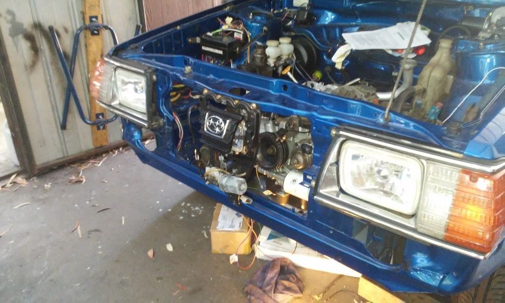
Sam that looks a treat in place there. I'm glad you will get to use it.
I had grand plans for it but my new brumby is Quad light and I didn't want to go hacking up a piece of Subaru history to get it to fit between the lights.
I have this stuff from USMB there was a PDF that went with it but the link is dead now.
http://www.ultimatesubaru.org/forum/top ... elaytimer/
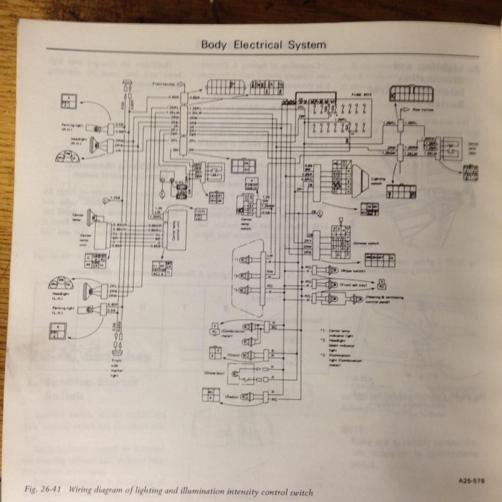

I hope the diagrams work for you
TOONGA
Posted: Sun Feb 07, 2016 8:12 am
by Nubaru
It would be COOL

to see this third eye work on arm /disarm of central locking when dark

Posted: Sun Feb 07, 2016 8:44 am
by Silverbullet
Jules, those pics are absolute GOLD!

Thankyou very much, they will be a massive help, I was looking for those files on USMB too and alas all the links were from 10+ years ago and long dead. I like factory wiring diagrams, and it even has the internal circuit schematic for that control board too. Awesome stuff.
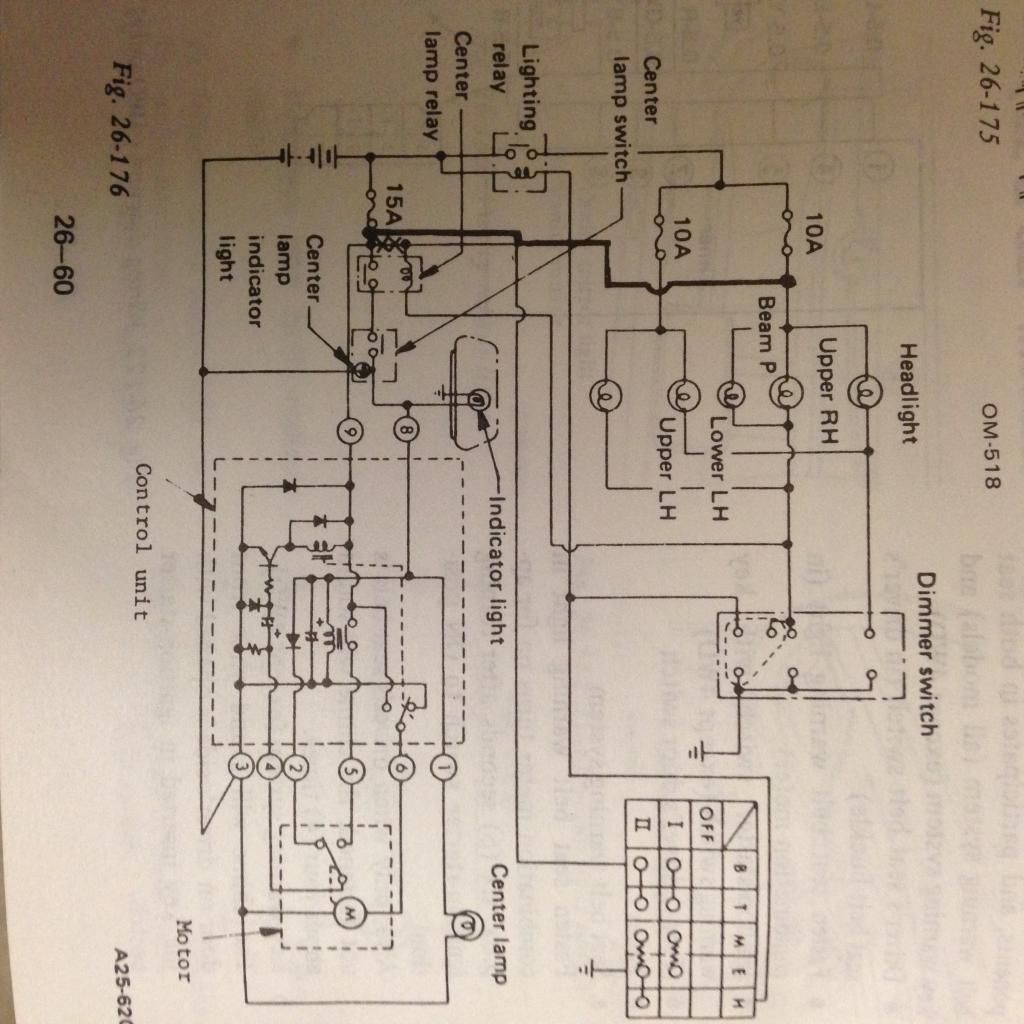
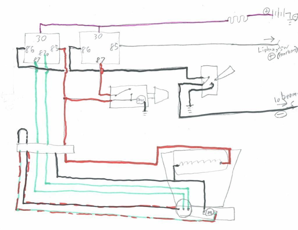
Bennie, pics below. There are only 2 wires coming in and they have their own 2 pin plug, wires soldered to the bottom of the board. The 6 output terminals all go to the motor/light plug and comprise of - for motor and light, + for light, + for motor, and the 3 left are little contacts in the gear box that open and close depending on where the door is in its cycle, a bit like a wiper motor self park function. With the above diagrams I'm sure it will be easy now to work out.
Nubaru, that is a feature well worth considering

Posted: Sun Feb 07, 2016 9:28 am
by TOONGA
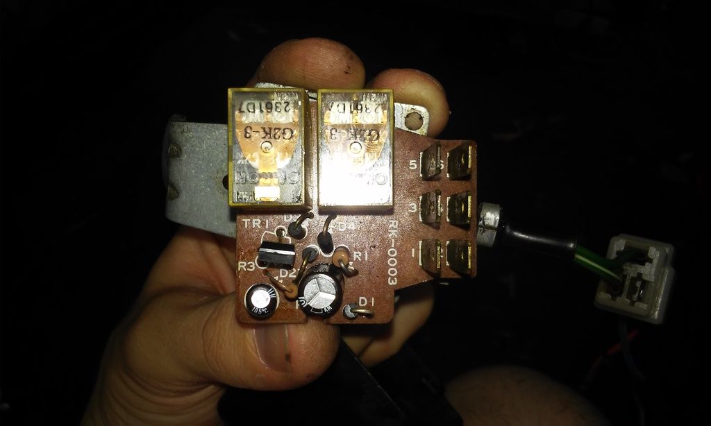
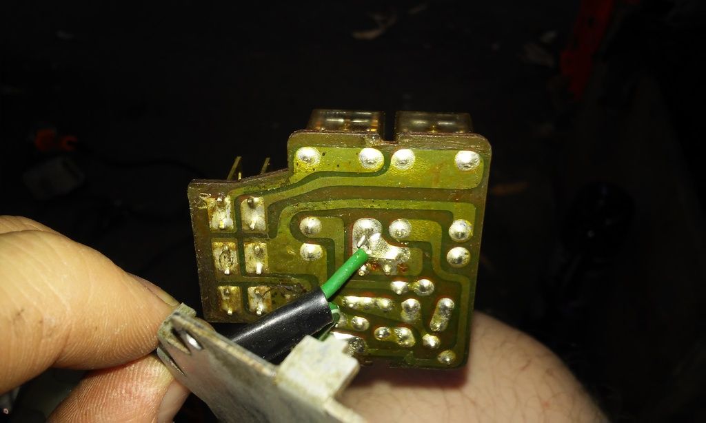
The back of that PCB is toast sorry Sam. I can see 2 sections where the copper has lifted from the board and is cooked.
It can be bypassed (solder a connecting wire from one terminal to the other) but it would be easier to make a new PCB or wire up your own relays and switch.
TOONGA
Posted: Sun Feb 07, 2016 11:03 am
by Silverbullet
Jules, I know

I noticed all that soon as I pulled the cover off. These photos were for my reference so I could draw it up on the PC and map out the circuit + components, but your pictures have saved me from doing that. Besides that, one of the little relays on the board was dead and the larger capacitor was puffed up and not capacitating any more
I did solder jumper wires to bypass the broken tracks, and removed the dead relay, piggy backed a modern relay onto the backside solder pads. And as luck would have it, we just happened to have a cheap 240v - 12v LED supply transformer blow up last week, which amazingly had the required cap to replace my dead one which I promptly pilfered
This was all just to get it working for now, I'm thinking I can put a new PCB mount relay back on the board and keep my insulated jumper wires in place, otherwise make a new board from scratch.
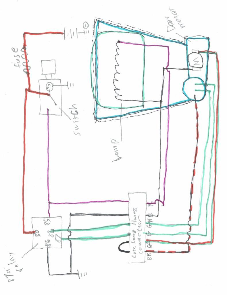
Turns out the 2 wires going to the underside of the PCB are constant 12v, and a 12v supply when you press the button. The ground is through one of the 6 pins. So some fiddling about and one butchered little PCB later I have this
https://www.youtube.com/watch?v=O_0ZQab ... e=youtu.be
Posted: Sun Feb 07, 2016 1:23 pm
by El_Freddo
Nice mate! That paint looks tops in the video!
Cheers
Bennie
Posted: Sun Feb 07, 2016 6:49 pm
by Silverbullet
All is well now
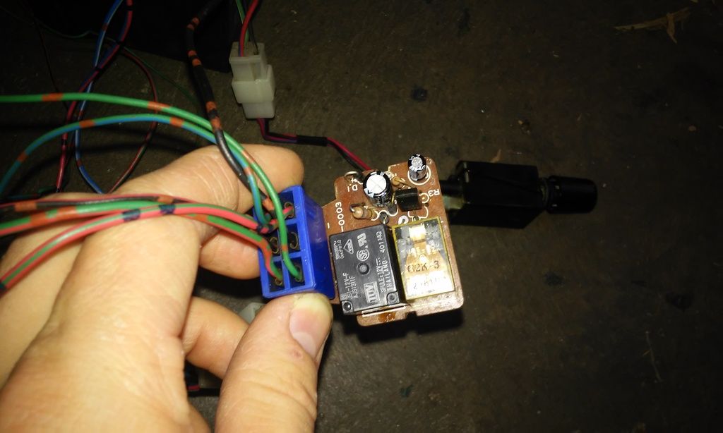
Got down to Jaycar this arvo and got the closest relay I could find to the original, it didn't drop straight in but I made it work in the end. The other capacitor was looking quite swelled as well so for 40c I replaced it with a new one. I put some permanent jumpers neatly around the place to bypass the broken tracks and covered the whole underside in liquid electrical tape. It works well and the new relay is doing its job nicely, so I think I will leave it like this until it dies then make a new board. Now just have to find somewhere to bolt the little control box and integrate the wiring into my loom.
New relay in place, works well
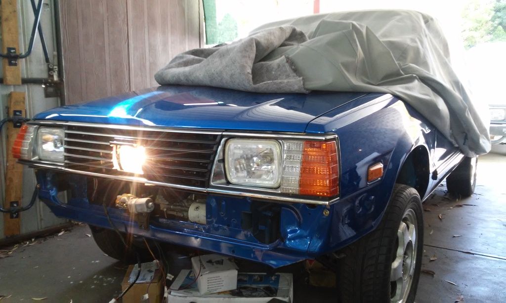
And one last pic because I love this light so much

Thought to myself, with the grille in place and the bonnet down the front end is looking scarily like a finished car. Just have to work out what I'm doing for a bumper bar, I'm thinking the single loop nudge bar style but can't find any decent reference pics.
Posted: Sun Feb 07, 2016 7:06 pm
by henpecked
I have a nudge bar if you want one -but its not the whole bumper
Posted: Sun Feb 07, 2016 7:43 pm
by Silverbullet
henpecked wrote:I have a nudge bar if you want one -but its not the whole bumper
Got any pics? steel or ally? I wouldn't be too bothered about not the whole bumper, I was planning on making one from scratch anyway.
Posted: Sun Feb 14, 2016 5:38 pm
by Silverbullet
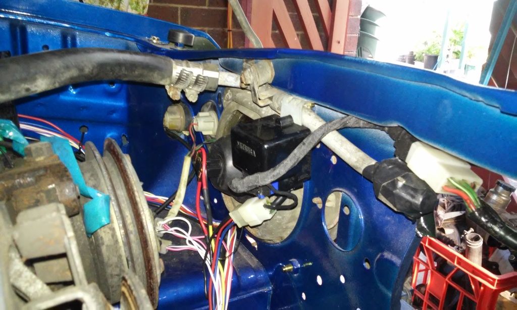
Today I finalized everything on the 3rd eye install, which meant fishing more wires around under the dash, wiring up another relay under the bonnet and finding a home for the control box (no idea where it is supposed to go originally)
Happy to say everything worked out tip top and I now have a fully working 3rd eye of enlightenment on my wagon. It can be turned on any time regardless of main headlights, but turns off automatically when you turn the engine off
Here's where the control box now lives; I made a new shorter harness to connect the light assembly to the box and wrapped it in loom tape. Because of this location, I'm thinking I'll take some extra measures to stop moisture getting into it, and any coolant that might get carelessly splashed around when filling the rad.
And a quick demo, not that you can see much from this angle but just to show the button works
https://www.youtube.com/watch?v=peAmolZ ... e=youtu.be
Posted: Sun Feb 14, 2016 10:48 pm
by Nubaru
has SA upgraded its rules to some level of sensibility re light bars etc ? Lights at the front in the past had to be in pairs. Some states now allow single light bars. And yu need to have your work of art inspected yet uhuh?
Posted: Mon Oct 03, 2016 2:53 pm
by Silverbullet