Dash wiring guide (Tach and VSS), for tacho dash conversion.
Posted: Mon Oct 08, 2018 4:47 pm
With the help of my multimeter, a 12V power supply, some bench space, and the suggestions of other members,
I have started to definitively map out the 4-gauge tacho dash, and the standard non-tacho dash.
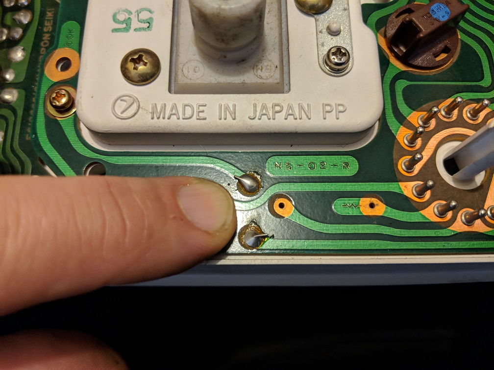
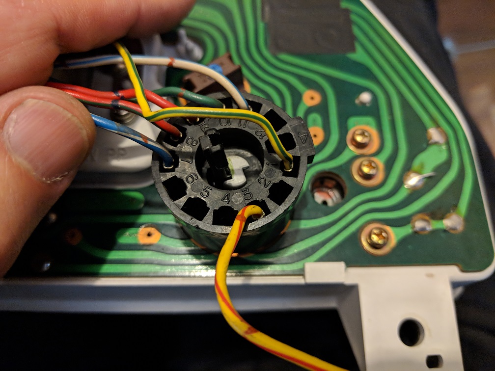
First of all the tacho wiring pin;
This is the PCB trace for the Tacho, marked "TA";
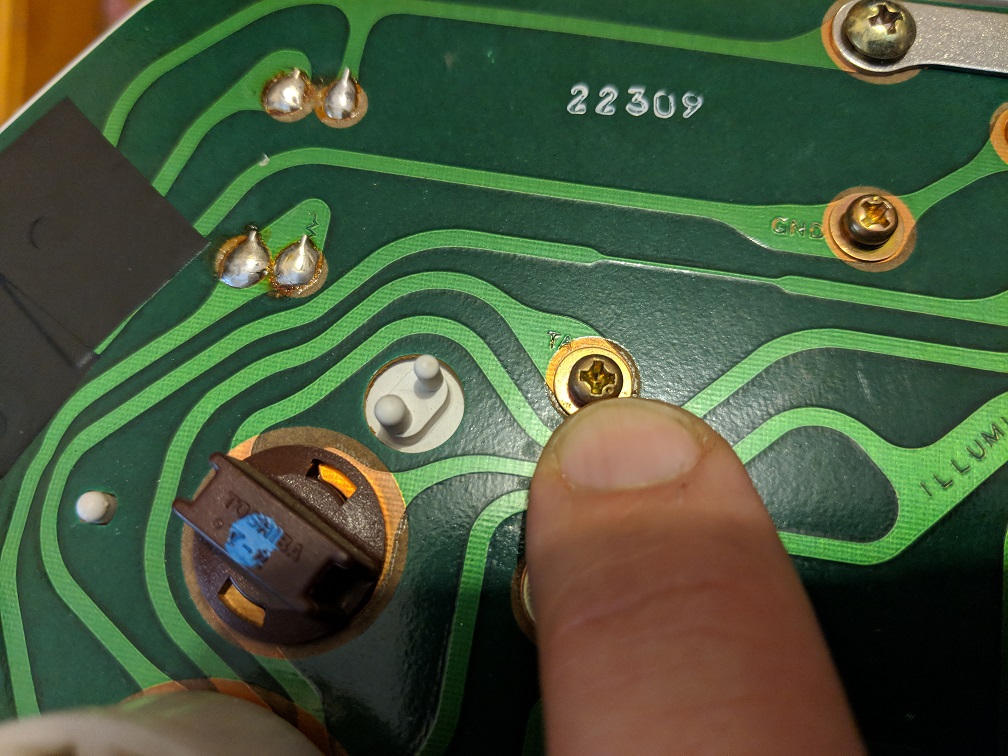
It goes to this pin;
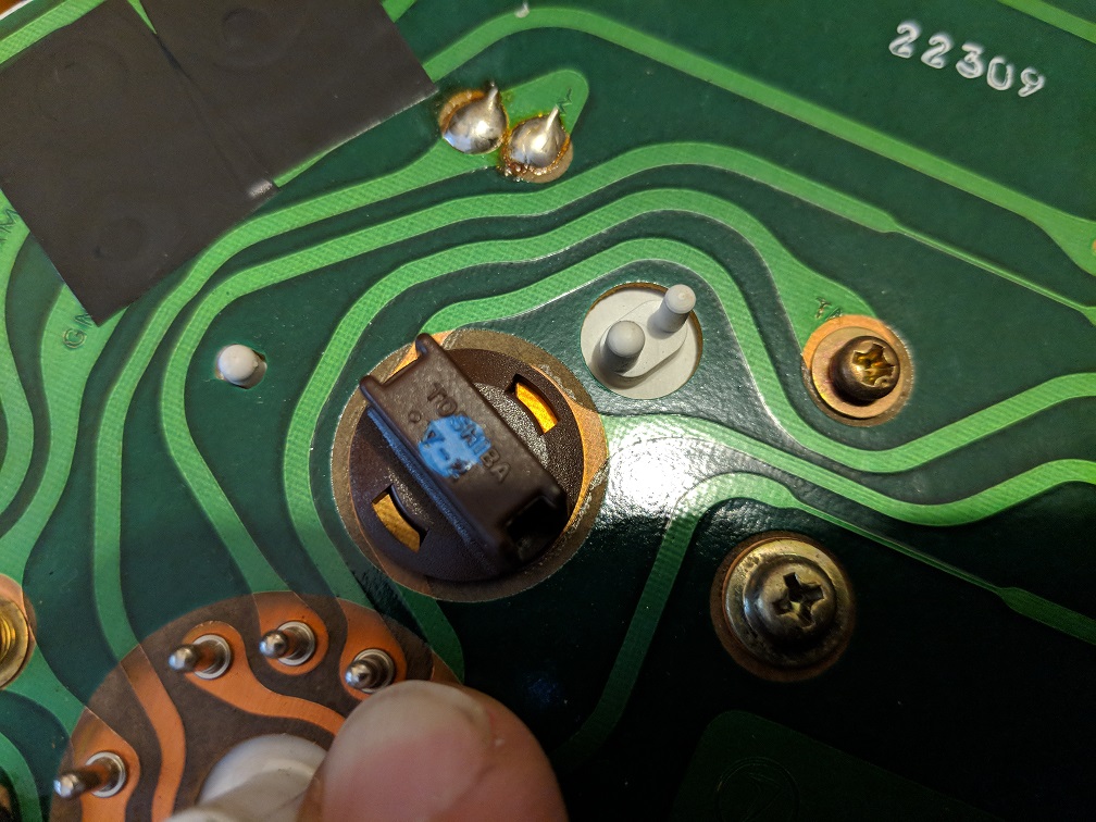
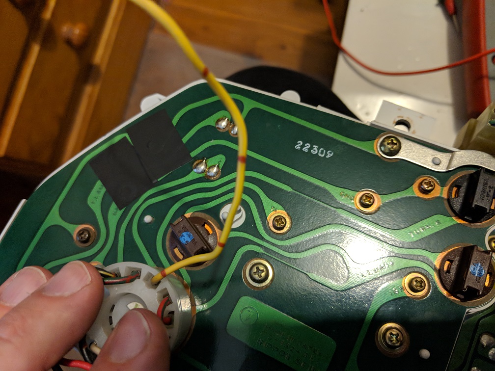
And becomes the yellow wire on the round white plug Pin 3;
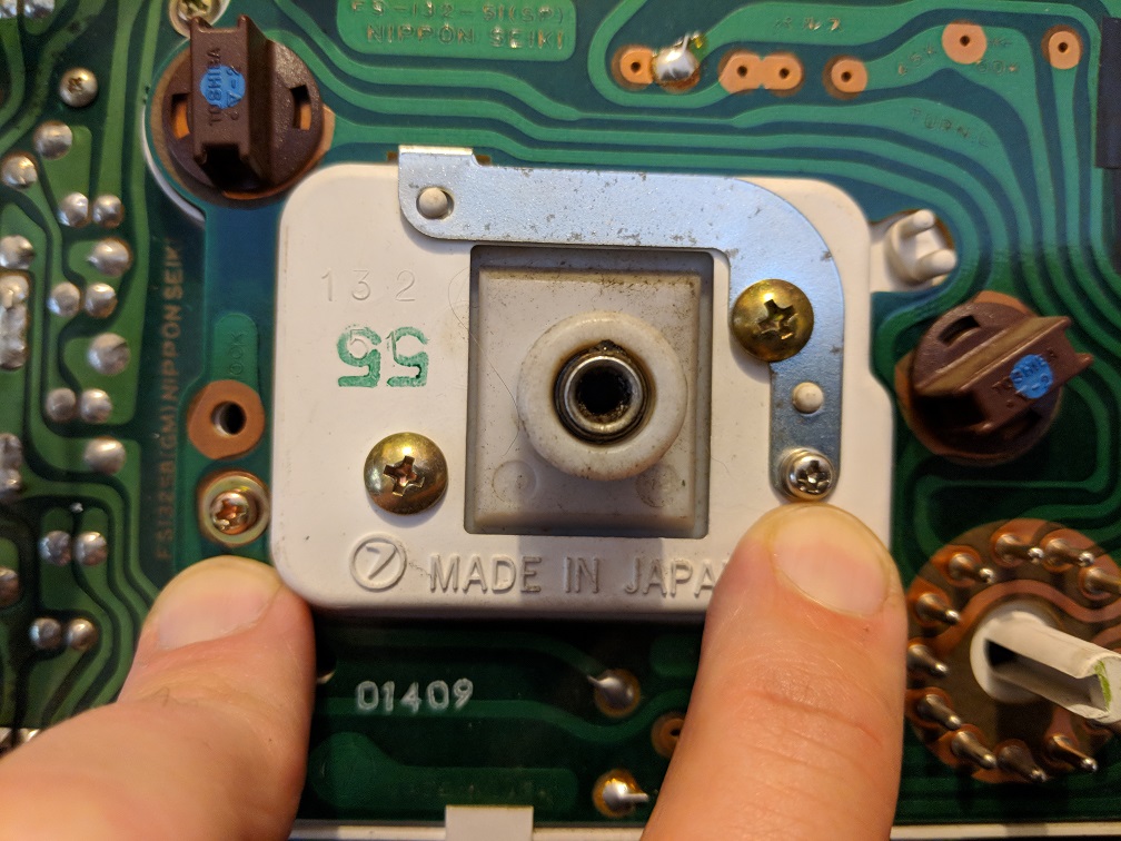
Next, the Vehicle Speed Sensor;
The tacho dash I have may or may not be from an MPFI (I can't find a "check engine" light on it).
However, I have pulled it apart and can report that it definitely has the reed switch fitted into the speedo, which is definitely not present in the non-tacho dash.
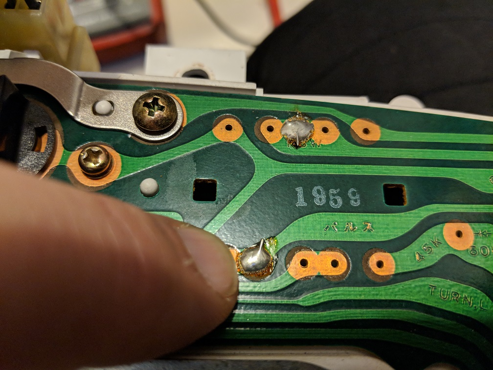
One side of the reed switch gets an ignition positive feed via the steel jumper strip across the top of the cluster, via the small screw on the right.
The other screw on the left is the output pulse from the reed.
The output side goes to a jumper;
The feed then snakes its way around the PCB to another jumper labelled "RSW", which matches the "RSW" on the reed switch;
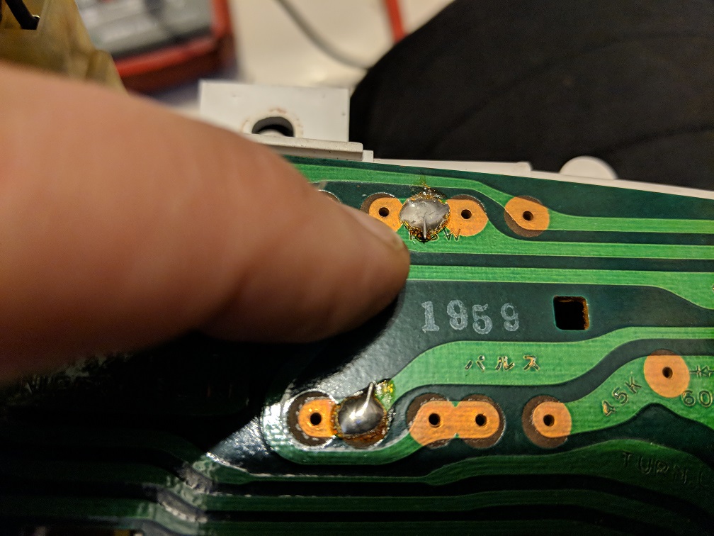
and back out;
and round to this pin;
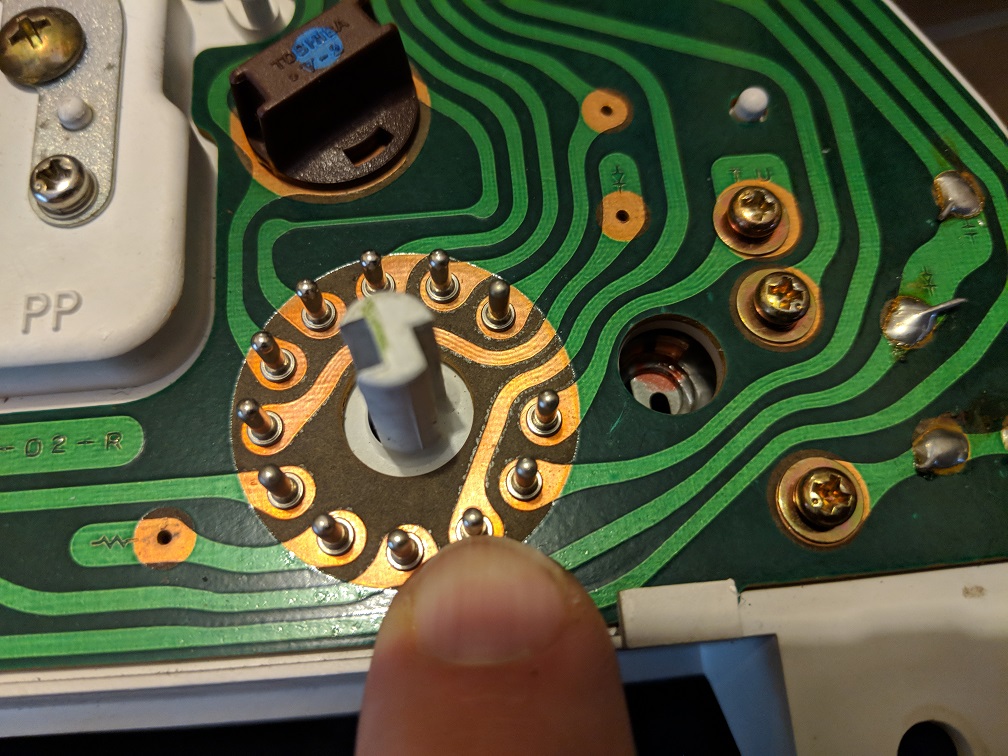
which attaches to this Yellow/Red wire on Pin 3 of the round black plug;
Here are the final charts, if it's blank, that means it's not fitted or not used on these particular dashes/cars;
First, the 1992 GL automatic;
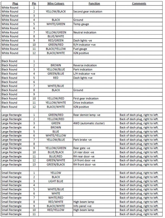
Now, the tach dash from a Touring Wagon;
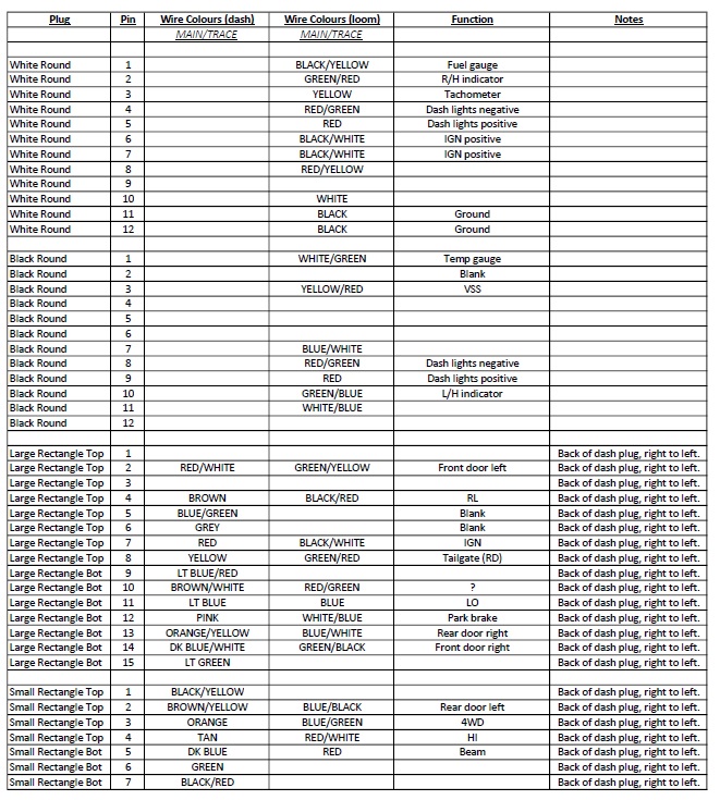
As you can see, some of the colours match up, some do not...
I have started to definitively map out the 4-gauge tacho dash, and the standard non-tacho dash.
First of all the tacho wiring pin;
This is the PCB trace for the Tacho, marked "TA";
It goes to this pin;
And becomes the yellow wire on the round white plug Pin 3;
Next, the Vehicle Speed Sensor;
The tacho dash I have may or may not be from an MPFI (I can't find a "check engine" light on it).
However, I have pulled it apart and can report that it definitely has the reed switch fitted into the speedo, which is definitely not present in the non-tacho dash.
One side of the reed switch gets an ignition positive feed via the steel jumper strip across the top of the cluster, via the small screw on the right.
The other screw on the left is the output pulse from the reed.
The output side goes to a jumper;
The feed then snakes its way around the PCB to another jumper labelled "RSW", which matches the "RSW" on the reed switch;
and back out;
and round to this pin;
which attaches to this Yellow/Red wire on Pin 3 of the round black plug;
Here are the final charts, if it's blank, that means it's not fitted or not used on these particular dashes/cars;
First, the 1992 GL automatic;
Now, the tach dash from a Touring Wagon;
As you can see, some of the colours match up, some do not...