Top effort mate.
The positive wire will most likely connect to an earth wire from the ECU to trigger the thermo fans and idle up when the compressor is engaged.
Impressive work once again!
How hard would it be to punch out this wiring for other to plug and play as a kit?
Cheers
Bennie
The RS6 - 1st gen Liberty EZ30D Conversion

-
Donkeytits1

- Junior Member
- Posts: 97
- Joined: Tue Feb 07, 2012 12:20 pm
- Location: Canberra
So I solved my problems today.
On closer inspection of the Gen 1 FSM, the engine electrics and the ABS system are completely separate, except for one wire that goes off to the alternator. Presented very descriptively like this
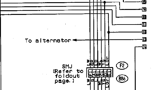
I have no idea where precisely it goes, but I can understand why the ABS system produces a warning light while the engine is running in another car - The alternator it's connected to isn't running. (The ABS system is connected to the alternator that's on the EJ22). This is also why there is a charge light, but that was obvious.
In the complete working Gen 1 I've noticed that if you unplug the alternator and turn on the ignition on, the ABS light lights up briefly then disappears on its own. I can reproduce that behaviour when the EZ is hooked in as well, and this leads me to be confident that the ABS system will be fine once everything is in the one engine bay and the alternator is connected and running.
As to why the ABS system relies on getting an alternator signal, I can only put this down to being a bit a bodge up on subaru's part for its first ABS equipped model. They needed a way for the ABS system to keep its warning light on to the point at which the engine starts (like all the other warning lights), and an easy way of doing that is to simply sense when the alternator has spun up. The alternative is change the ECU firmware to talk to the ABS module, which is more involved.
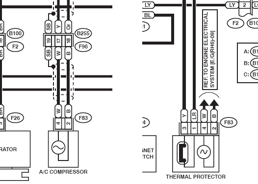
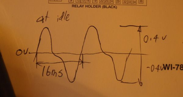
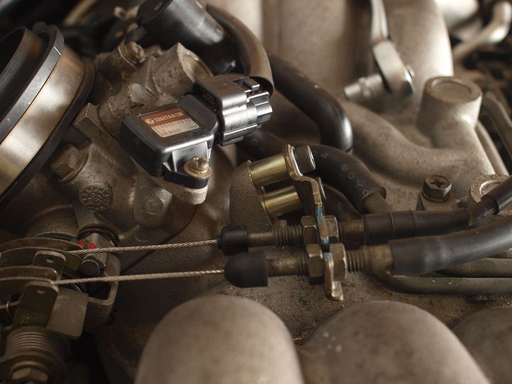
As for the A/C, that little thing in the thermal cutout is actually a magnetic speed sensor for the compressor shaft. It's built into the side of the compressor unit. How they've shown that in the manual is a bit misleading, if you ask me. It has nothing to do with the thermal cutout, and whilst it does give a roughly sinusoidal AC output, its not really a power supply; Its a sensor, so why not represent it like all the other sensors. Anyway, It is the same type of sensor that is commonly used for crank angle, and it gives a similar shaped signal. Here's a sketch of what it does at idle. At speed, the voltage increases to around +- 1.2V and the frequency increases of course.
Without this signal, the ECU will engage the magnet clutch for around 3 seconds until it drops it and will not re energize the magnet clutch until the engine is switched off and restarted. My guess is this is to detect a slipping magnet clutch or a seized compressor. This is in a car with climate control, so it automatically engages the A/C without the driver thinking too much about it, so i guess that's why there is that added level of protection. Its also why it is in the H6 and not the pov pack 4cyl variants.
Luckily the logic in the ECU is dumb enough that it will accept a constant square wave of an unrelated frequency. And it also doesn't seem to mind if its getting a signal while the compressor is not supposed to be spinning ie, when the A/C is switched off. Conveniently, there are a few wave signals we can source from, an easy one being the taco signal. So all I've done is drop the taco signal down to 1.2V or so and fed it into the input for this sensor. Appears to work.
Tomorrow, just need to buy a couple of resistors to fine tune the Taco circuit, now that it has this modification the actual taco goes dodgy if the battery voltage drops a bit.
El Freddo: The A/C is a bit more complicated than that
The gen 1 essentially has a cut loop - One ECU pin is energised when all the switches and relays want the compressor to run, and there is another pin that actually energises the final relay to run the magnet clutch. This is so the ECU can control the AC and cut it when your accelerating hard. The EZ has those loop pins, but it also has a blower sense (sensing when the blower motors on) mid pressure sense that goes to the pressure cut off switch (which appears not to effect what the ECU does at all) and that annoying shaft speed sensor. PITA. Its wired up now by basically grounding the appropriate blower and pressure sense pins and running that square wave into the sensor input. Now it just runs like the old Gen 1 system.
Yeah this could probably be knocked up into a kit.
The board should be easy enough to punch out. Need to make some amendments, but sending them off to get fabbed wouldn't be a problem. Will probably do that anyway so that I have a nice clean board with no bodges in the car.
And I could program a bunch of micros easily enough to send out with the boards.
Time to buy a GX or a GC8 and start another project mate
On closer inspection of the Gen 1 FSM, the engine electrics and the ABS system are completely separate, except for one wire that goes off to the alternator. Presented very descriptively like this
I have no idea where precisely it goes, but I can understand why the ABS system produces a warning light while the engine is running in another car - The alternator it's connected to isn't running. (The ABS system is connected to the alternator that's on the EJ22). This is also why there is a charge light, but that was obvious.
In the complete working Gen 1 I've noticed that if you unplug the alternator and turn on the ignition on, the ABS light lights up briefly then disappears on its own. I can reproduce that behaviour when the EZ is hooked in as well, and this leads me to be confident that the ABS system will be fine once everything is in the one engine bay and the alternator is connected and running.
As to why the ABS system relies on getting an alternator signal, I can only put this down to being a bit a bodge up on subaru's part for its first ABS equipped model. They needed a way for the ABS system to keep its warning light on to the point at which the engine starts (like all the other warning lights), and an easy way of doing that is to simply sense when the alternator has spun up. The alternative is change the ECU firmware to talk to the ABS module, which is more involved.
As for the A/C, that little thing in the thermal cutout is actually a magnetic speed sensor for the compressor shaft. It's built into the side of the compressor unit. How they've shown that in the manual is a bit misleading, if you ask me. It has nothing to do with the thermal cutout, and whilst it does give a roughly sinusoidal AC output, its not really a power supply; Its a sensor, so why not represent it like all the other sensors. Anyway, It is the same type of sensor that is commonly used for crank angle, and it gives a similar shaped signal. Here's a sketch of what it does at idle. At speed, the voltage increases to around +- 1.2V and the frequency increases of course.
Without this signal, the ECU will engage the magnet clutch for around 3 seconds until it drops it and will not re energize the magnet clutch until the engine is switched off and restarted. My guess is this is to detect a slipping magnet clutch or a seized compressor. This is in a car with climate control, so it automatically engages the A/C without the driver thinking too much about it, so i guess that's why there is that added level of protection. Its also why it is in the H6 and not the pov pack 4cyl variants.
Luckily the logic in the ECU is dumb enough that it will accept a constant square wave of an unrelated frequency. And it also doesn't seem to mind if its getting a signal while the compressor is not supposed to be spinning ie, when the A/C is switched off. Conveniently, there are a few wave signals we can source from, an easy one being the taco signal. So all I've done is drop the taco signal down to 1.2V or so and fed it into the input for this sensor. Appears to work.
Tomorrow, just need to buy a couple of resistors to fine tune the Taco circuit, now that it has this modification the actual taco goes dodgy if the battery voltage drops a bit.
El Freddo: The A/C is a bit more complicated than that
The gen 1 essentially has a cut loop - One ECU pin is energised when all the switches and relays want the compressor to run, and there is another pin that actually energises the final relay to run the magnet clutch. This is so the ECU can control the AC and cut it when your accelerating hard. The EZ has those loop pins, but it also has a blower sense (sensing when the blower motors on) mid pressure sense that goes to the pressure cut off switch (which appears not to effect what the ECU does at all) and that annoying shaft speed sensor. PITA. Its wired up now by basically grounding the appropriate blower and pressure sense pins and running that square wave into the sensor input. Now it just runs like the old Gen 1 system.
Yeah this could probably be knocked up into a kit.
The board should be easy enough to punch out. Need to make some amendments, but sending them off to get fabbed wouldn't be a problem. Will probably do that anyway so that I have a nice clean board with no bodges in the car.
And I could program a bunch of micros easily enough to send out with the boards.
Time to buy a GX or a GC8 and start another project mate
-
Donkeytits1
- Junior Member
- Posts: 97
- Joined: Tue Feb 07, 2012 12:20 pm
- Location: Canberra
So I dived into the mechanical side of the project earlier in the week.
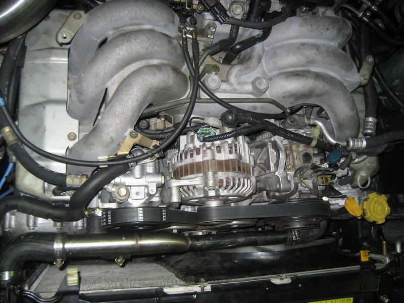
The engine is a BEAST. The big cam chain cover makes the engine look absolutely massive. I'm worried if its even going to fit in! (Although it's certain it does).
The alternator on the EZ is a bit larger, higher capacity and has a small 3 pin connector along with the main terminal. This is different to the early EJ which has a round 4 pin connector. I happen to have a spare EJ alternator, and as I am using the original front harness and I don't need the extra generating capacity, I've decided to modify the EJ alt to fit the EZ. This wasn't hard, basically it just involved swapping the pulleys.
Both alternators had noisy bearings, so I overhauled the EJ alternator and ripped the pulley off the EZ. The shaft protrudes the same amount out of both alternators relative to the mounting holes, but the front bearing on the EZ alternator is set back 3.5 - 4mm further than the Hitachi EJ alternator. Because of this the exposed section of the shaft is 4mm longer, the pulley is 4mm longer to count for it. They could have used a 4mm spacer, but I guess its cheaper to change the design of the pulley. So, threw the pulley on the lathe at work, cut 4mm off the back of it, rattled it onto the EJ alt, no problems. Lined it up at home on the engine, everythings sweet.
Tossing up weather to replace the plugs. They are an absolute c*** to change when they are in the car, and they are iridium platinums, so they cost around $250 bucks for a set from the local parts place, or you've got to wait up to two weeks to get a $150 set off eBay.
Keen to keep the upfront cost of this conversion low, in case it turns out to be shit and I decide to swap back. And waiting two weeks would suck ass, so I think I'll give them a miss. The engine has 180k on it, and I have all the service history. So as the plugs have a supposed life of 100k, I should about a year and a half left in them if they all decide to go AT the service interval. I'll risk it, and get that biscuit.
Just gotta quickly rip the head covers off and check the valve clearances, hopefully they're OK. Should be, the engine's very quiet and smooth. After that Its time to say bubye daily and pull the EJ out.
Will add a few pics to this post soon
-
FROG

- General Member
- Posts: 1409
- Joined: Fri Feb 23, 2007 12:41 pm
- Location: UNDER THE SOUTHERN CROSS GRIFFITH NSW
- Contact:
I can supply the plugs for $33 each at mates rates if that helps
GRAB THE VIN FROM DONOR VEHICLES
AUSubaru member specials
Brumby EA81 Oil Pump kit (4 x 'o'rings + gasket) posted Australia wide $22!
Brumby sloppy shifter bush kit $44 posted
email me
http://www.domsmotors.com.au
NOW DISTRIBUTING FOR SUBAXTREME BASH PLATES, NUDGE AND BULLBARS
-
Donkeytits1
- Junior Member
- Posts: 97
- Joined: Tue Feb 07, 2012 12:20 pm
- Location: Canberra
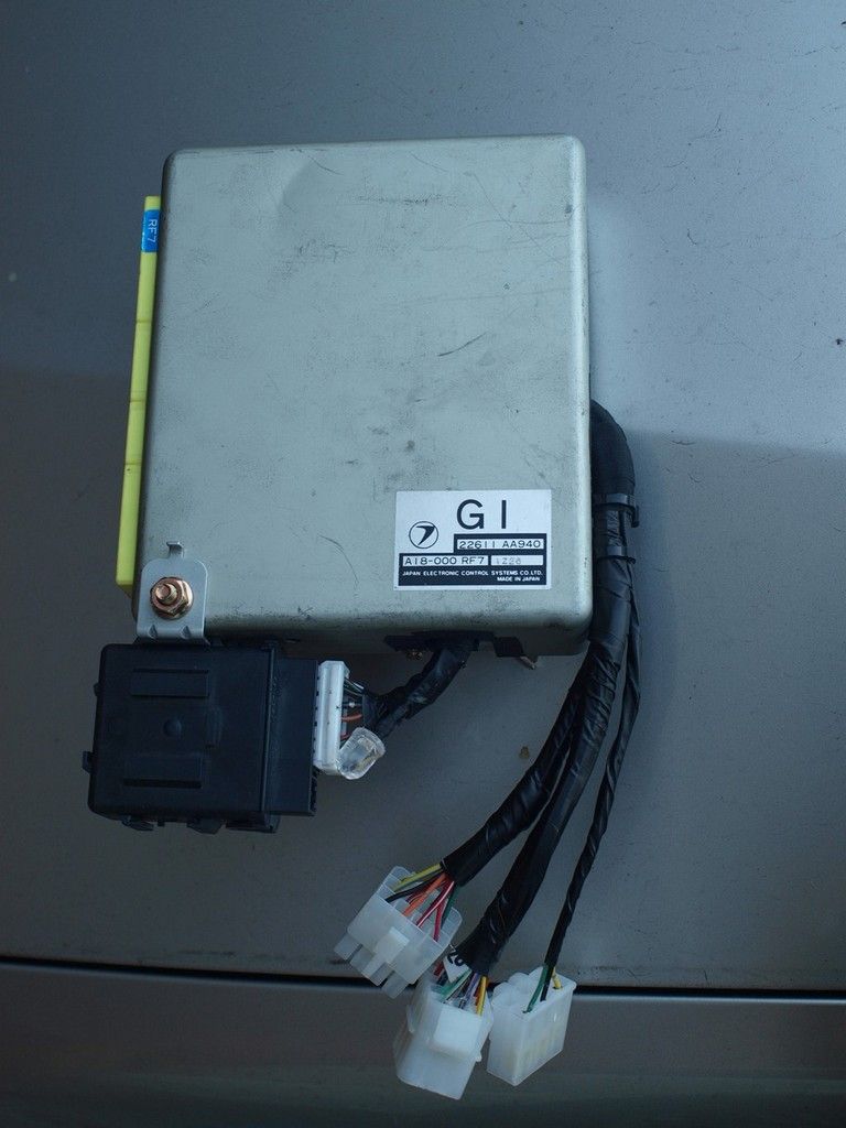
Put the finishing touches in the interface board. The only thing missing is some epoxy to give the wire connections some vibration resistance and stress relief.
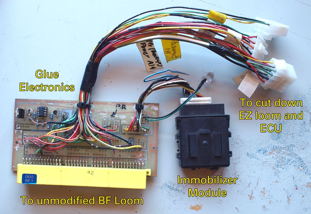
I added connectors between the board and the rest of the loom, so that if I need to modify it or repair it I need to. The whole thing will be mounted in the stock BC/BF ECU case, with some holes cut in the side.
The immobilizer module sits neatly to the side, and will be mounted to the side of the case with a small bracket I salvaged from the donor car.
You can see this is still V1.0 of the board, and there are a couple of bodges. There are some cut tracks on the underside and some bodge wires, and on the top you can see the small brown wire and the doubled up resistors I added to simulate the A/C shaft speed sensor.
If I was to make V2 of this board, I would probably order in a board mounted connector and matching plug and do away with the wires soldered directly to the board. This would make the whole thing much more reliable, neater and easy to make. I would also leave the immobilizer connections off the board and have the plug run directly from the cut down EZ loom, seeing as there are no connections to the glue electronics or the BC/BF loom except for power. But after saying all that, this will work well enough I hope
The immobilizer LED is just floating for the time being. Eventually I'll rig up a proper LED in the dash cluster.
Oh, and that floating blue wire on the immobilizer is the door warning wire. Originally thought it needed to be grounded when the door was closed, but found out its grounded when the doors open. Not sure why it needs to know that information, maybe to boot up and be ready for a start, but it draws power and seems to work fine thinking the doors constantly closed.
-
Donkeytits1
- Junior Member
- Posts: 97
- Joined: Tue Feb 07, 2012 12:20 pm
- Location: Canberra
So today I mounted the board in its enclosure and installed it in the car.
A few days ago I welded screws onto the EZ ECU and it mounts neatly behind the old ECU/inteface board where the TCU is mounted in automatic cars.
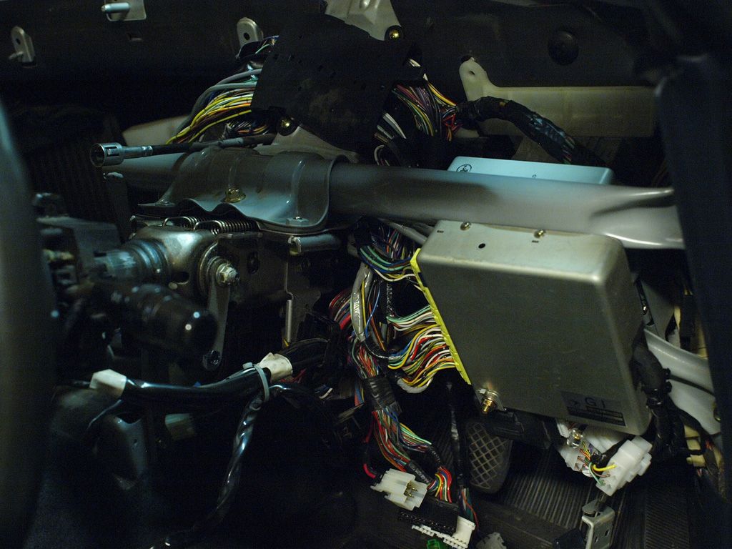
The cable tray above the steering column will happily take all the extra EZ wires.
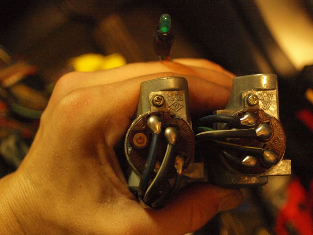
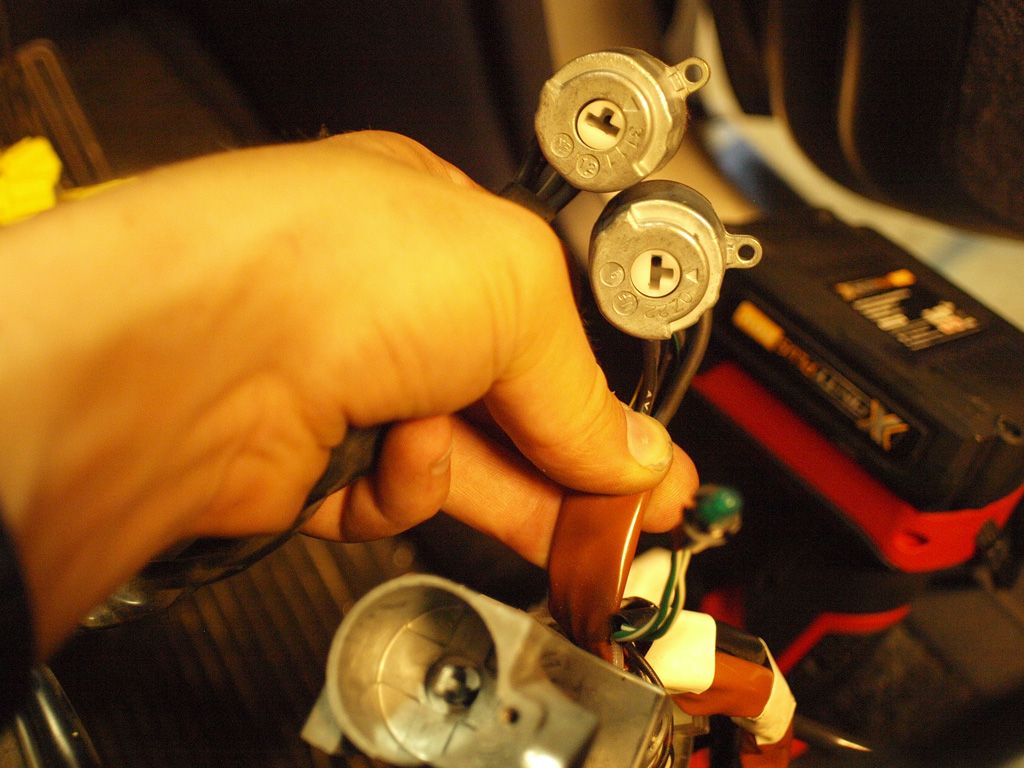
I'm using the key barrel off the EZ car. I haven't worked out why the immobilizer needs it to run or whether the old barrel will work with the immobilizer as well. But I can be sure it will work, and the fob antenna fits over it nicer. The old barrel is also getting pretty worn. I'll need two keys on my keyring now.
The old barrels are both compatable with the steering column, bar the square key on the EZ barrel. I'll need to sculpt out the column a little to make that work.
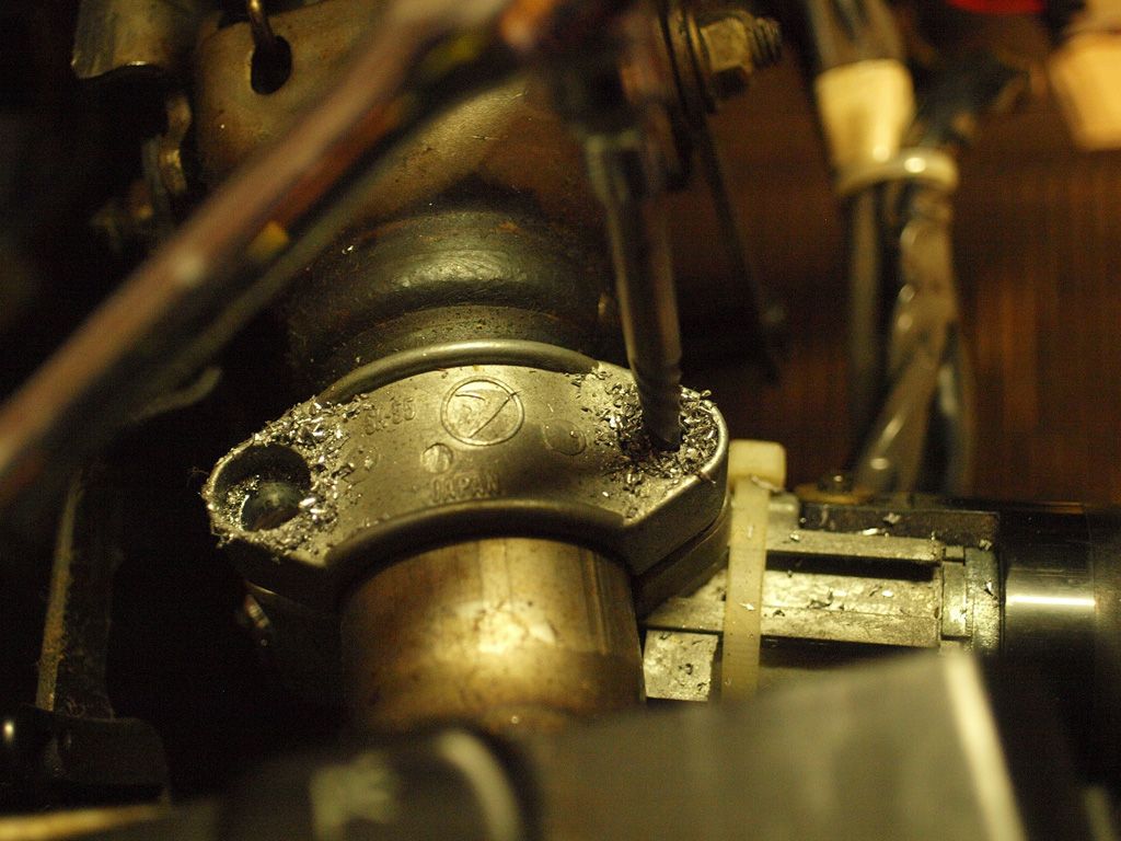
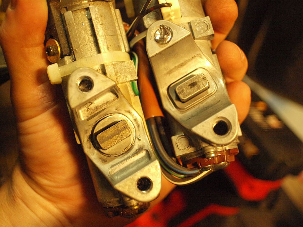
The plugs on the end are different, but that doesn't matter because the actuall switches will actually swap over.
A few days ago I welded screws onto the EZ ECU and it mounts neatly behind the old ECU/inteface board where the TCU is mounted in automatic cars.
The cable tray above the steering column will happily take all the extra EZ wires.
I'm using the key barrel off the EZ car. I haven't worked out why the immobilizer needs it to run or whether the old barrel will work with the immobilizer as well. But I can be sure it will work, and the fob antenna fits over it nicer. The old barrel is also getting pretty worn. I'll need two keys on my keyring now.
The old barrels are both compatable with the steering column, bar the square key on the EZ barrel. I'll need to sculpt out the column a little to make that work.
The plugs on the end are different, but that doesn't matter because the actuall switches will actually swap over.
-
Bantum

- Senior Member
- Posts: 2042
- Joined: Sun Jul 29, 2012 4:30 pm
- Location: Northern Territory + QLD
- Contact:
OBD Protocol ...
Yes - the plan was to run it via a compliant cpu as an overlay system - with it 'monitoring' the basic functions ( wouldn't actually need to run half the other stuff ). You would have to make sure the module is OBDII first though.Donkeytits1 wrote: ... Hmm. Not sure how you're going to go with that Bantum, those things are designed to work on the OBDII protocol ?
P.S. - Inspiring work with the board you have done, any plans to release the drawings for this ?
Cheers, Bantum ...
-
Donkeytits1
- Junior Member
- Posts: 97
- Joined: Tue Feb 07, 2012 12:20 pm
- Location: Canberra
-
Donkeytits1
- Junior Member
- Posts: 97
- Joined: Tue Feb 07, 2012 12:20 pm
- Location: Canberra
-
Donkeytits1
- Junior Member
- Posts: 97
- Joined: Tue Feb 07, 2012 12:20 pm
- Location: Canberra
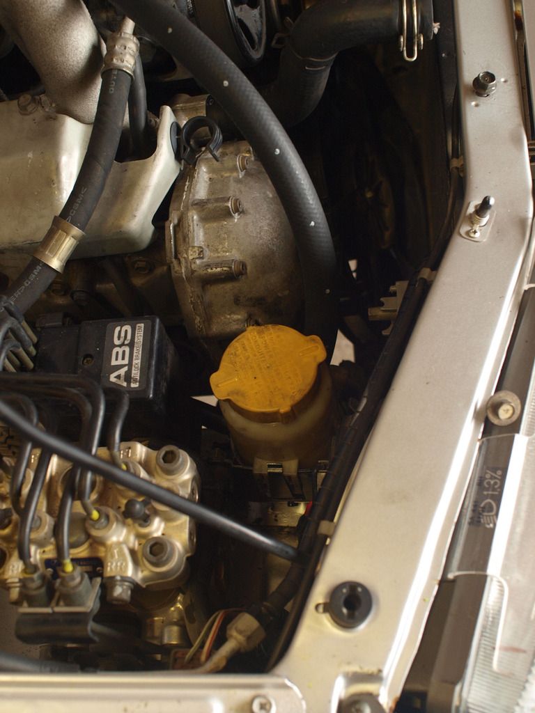
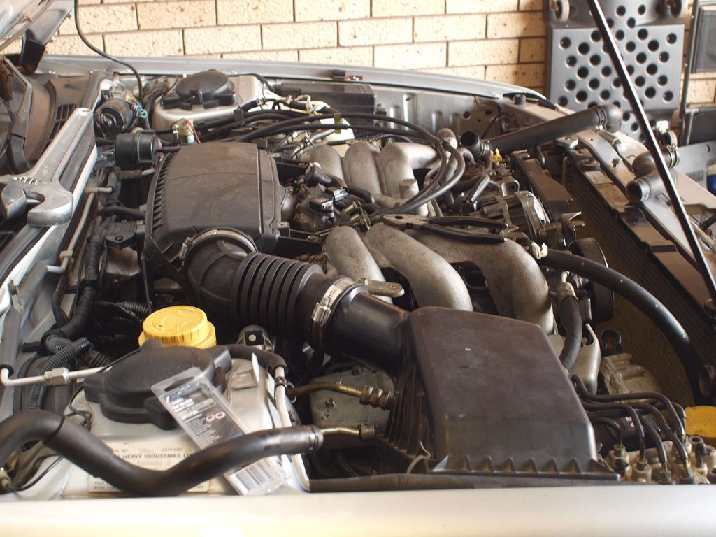
So now that the engine is in and running, the hurdles are fabrication and packaging related.
Flywheel and clutch went straight on, and the engine went straight in with a bit of manoeuvring. The steel injector rail cover on the left hand side needs to come off so that you can clear the cruise control pump and that's it. Engine was easy to slip onto the tranny with the tranny jacked up and the engine on a tilt adjuster. Tranny engine bolts have plenty of access like it was with the EJ, and the lower engine mounts dropped into their holes without fuss. Every thing is pretty tight in there, with only 15-20mm clearance between alot of things. But nothing hits when the engine kicks.
The top of the engine looks high when its all sitting there. But the hood still clears the engine, even with the beauty cover on. I've only confirmed this by laying a piece of corrugated cardboard down on top of the engine and looking for indents, so I don't know if the gap is 25mm or 5mm. All I know its a 4mm piece of card can fit in between. I'm not worried about damaging the hood with this though. If there is contact, it will be between the flat plastic beauty cover and bonnet ribs, and the extent of the engine movement I have so far observed is not likely to damage or bend anything. I'm just going to suck it and see.
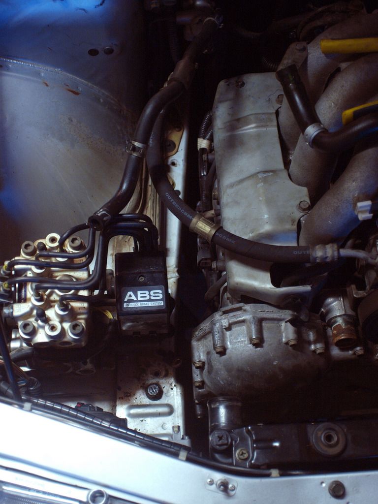
Power steering and feed lines are swapped over as the EZ has a remote reservoir. Cannot use the EJ pump because the integrated reservoir fouls on the intake manifold of the EZ. It is a straight forward swap though, the fittings on the steering rack are the same and the hard lines only need a small amount of bending to adapt to the different hole positions. This can be achieved with a set of multigrips.
The A/C system is all EJ. The hardlines on the compressor need a little bending. The one that goes to the front condenser needs to be bent so that it can clear the intake manifold. The one the runs back to the firewall to feed the evaporator needs to be straightened out a bit to give about an inch more length to account for the longer engine. I tried to do this with the refrigerant charge still in the system, but it was too hard to hold the compressor and bend the lines at the same time. The lines are too strong. Access to the lines around the firewall is limited, and the connection to the evaporator isn't rigid enough to bend the pipes. So I had to recover the refrigerant and bend the compressor lines with the compressor mounted and the connections partially undone. The evaporator line needed to be removed and held in a vice.
The challenges not are fitting the exhaust and finding a suitable gearbox cross member, and sorting out a cooling solution.
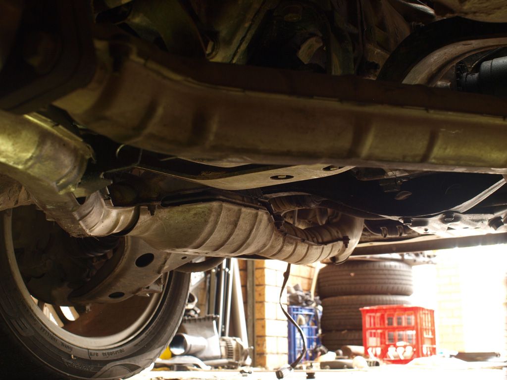
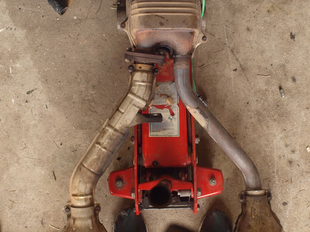
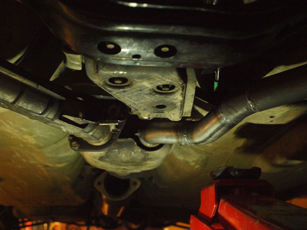
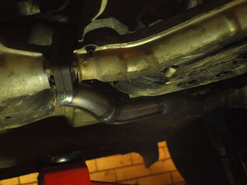
The issue with the crossmember is that the stock H6 headers fit fine - they align with the exhaust hanger and everything - but they interfere with the crossmember in two places. One is on forward LH Side where the crossmember is not sculpted to provide room for an exhaust (see photo) and around the hanger where the two portions of the exhaust merge, one side interferes with the rearmost central sections of the crossmember. I 'have' to use these headers, because they have 3 cats in them and they have pre and post O2 sensors. So deleting cats causes more ECU problems, and buying 3 new cats is expensive. Don't really want to cut and shut the headers as I'd loose all the heat shielding and if I ever needed to replace them it would be another custom job. The rear cat would need quite a dodgy joint aswell. I've been researching crossmembers the last couple of days, and asked a few subaru nuts, and the results of this are that turbo cross members have the LH side sculpted for dual exhausts, and it seems some versions also have more clearance around the exhaust hanger too. The bolt pattern at the chassis is the same. So once wreckers are staffed again, I'll go for a look around and see if I can avoid modifying the exhaust. Who thought a 2001 6 cyl exhaust would fit under a 1993 4 cyl car?? stoked.

[Credit: Team Scream at Subaruforester.org]
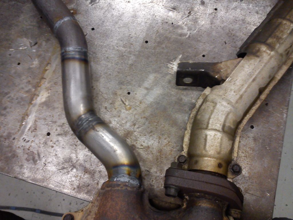
Picked up a full 3" stainless steel exhaust system for a turbo RS liberty a week or two ago for $100. Again, stoked. A slight modification should see that mate up to the headers nicely. And stainless is nice to weld
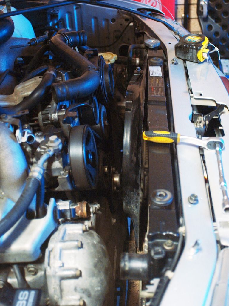
Up front, cooling is an issue, and I think the only good solution is a custom radiator. As the engine is 1 to two inches longer than the EJ, space up front is suddenly at a premium. The fact the that EZ has two outlets at the top is also a complication. The EZ and EJ radiators are essentially the same size, but the EZ has a top bottom tank design and the lower rad outlet is dropped down an inch or two below the bottom tank. This interferes with the chassis on the new car. The EJ radiator still drops in, and I have dodged up a manifold that can join the two coolant outlets. But there is absolutely no space left for rad fans that way. Seeing as I don't want to modify the chassis or the rad support, the only solution really is a top tank aluminium radiator with slimline fans. This will allow me to use the stock EZ hoses, which will be neat and leave enough length for good hose flex, and there will be space for some slimline fans. Dunno how much it will cost though. Depends how modular they are. In the mean time, I'll use the dodged up manifold and have no radiator fans. I think fans will be a necessity, as the front of the engine is so big and flat! Its like the air comes through the radiator and hits a brick wall. So while passive cooling was never a problem with the EJ, now we will probably have a reduction of passive airflow and when driving hard there will be at worst a 60% increase in cooling load. I guess again, we'll suck it an see. Not like I can shave the sides of the cam cover off or anything.
Will keep youze updated
Flywheel and clutch went straight on, and the engine went straight in with a bit of manoeuvring. The steel injector rail cover on the left hand side needs to come off so that you can clear the cruise control pump and that's it. Engine was easy to slip onto the tranny with the tranny jacked up and the engine on a tilt adjuster. Tranny engine bolts have plenty of access like it was with the EJ, and the lower engine mounts dropped into their holes without fuss. Every thing is pretty tight in there, with only 15-20mm clearance between alot of things. But nothing hits when the engine kicks.
The top of the engine looks high when its all sitting there. But the hood still clears the engine, even with the beauty cover on. I've only confirmed this by laying a piece of corrugated cardboard down on top of the engine and looking for indents, so I don't know if the gap is 25mm or 5mm. All I know its a 4mm piece of card can fit in between. I'm not worried about damaging the hood with this though. If there is contact, it will be between the flat plastic beauty cover and bonnet ribs, and the extent of the engine movement I have so far observed is not likely to damage or bend anything. I'm just going to suck it and see.
Power steering and feed lines are swapped over as the EZ has a remote reservoir. Cannot use the EJ pump because the integrated reservoir fouls on the intake manifold of the EZ. It is a straight forward swap though, the fittings on the steering rack are the same and the hard lines only need a small amount of bending to adapt to the different hole positions. This can be achieved with a set of multigrips.
The A/C system is all EJ. The hardlines on the compressor need a little bending. The one that goes to the front condenser needs to be bent so that it can clear the intake manifold. The one the runs back to the firewall to feed the evaporator needs to be straightened out a bit to give about an inch more length to account for the longer engine. I tried to do this with the refrigerant charge still in the system, but it was too hard to hold the compressor and bend the lines at the same time. The lines are too strong. Access to the lines around the firewall is limited, and the connection to the evaporator isn't rigid enough to bend the pipes. So I had to recover the refrigerant and bend the compressor lines with the compressor mounted and the connections partially undone. The evaporator line needed to be removed and held in a vice.
The challenges not are fitting the exhaust and finding a suitable gearbox cross member, and sorting out a cooling solution.
The issue with the crossmember is that the stock H6 headers fit fine - they align with the exhaust hanger and everything - but they interfere with the crossmember in two places. One is on forward LH Side where the crossmember is not sculpted to provide room for an exhaust (see photo) and around the hanger where the two portions of the exhaust merge, one side interferes with the rearmost central sections of the crossmember. I 'have' to use these headers, because they have 3 cats in them and they have pre and post O2 sensors. So deleting cats causes more ECU problems, and buying 3 new cats is expensive. Don't really want to cut and shut the headers as I'd loose all the heat shielding and if I ever needed to replace them it would be another custom job. The rear cat would need quite a dodgy joint aswell. I've been researching crossmembers the last couple of days, and asked a few subaru nuts, and the results of this are that turbo cross members have the LH side sculpted for dual exhausts, and it seems some versions also have more clearance around the exhaust hanger too. The bolt pattern at the chassis is the same. So once wreckers are staffed again, I'll go for a look around and see if I can avoid modifying the exhaust. Who thought a 2001 6 cyl exhaust would fit under a 1993 4 cyl car?? stoked.
[Credit: Team Scream at Subaruforester.org]
Picked up a full 3" stainless steel exhaust system for a turbo RS liberty a week or two ago for $100. Again, stoked. A slight modification should see that mate up to the headers nicely. And stainless is nice to weld
Up front, cooling is an issue, and I think the only good solution is a custom radiator. As the engine is 1 to two inches longer than the EJ, space up front is suddenly at a premium. The fact the that EZ has two outlets at the top is also a complication. The EZ and EJ radiators are essentially the same size, but the EZ has a top bottom tank design and the lower rad outlet is dropped down an inch or two below the bottom tank. This interferes with the chassis on the new car. The EJ radiator still drops in, and I have dodged up a manifold that can join the two coolant outlets. But there is absolutely no space left for rad fans that way. Seeing as I don't want to modify the chassis or the rad support, the only solution really is a top tank aluminium radiator with slimline fans. This will allow me to use the stock EZ hoses, which will be neat and leave enough length for good hose flex, and there will be space for some slimline fans. Dunno how much it will cost though. Depends how modular they are. In the mean time, I'll use the dodged up manifold and have no radiator fans. I think fans will be a necessity, as the front of the engine is so big and flat! Its like the air comes through the radiator and hits a brick wall. So while passive cooling was never a problem with the EJ, now we will probably have a reduction of passive airflow and when driving hard there will be at worst a 60% increase in cooling load. I guess again, we'll suck it an see. Not like I can shave the sides of the cam cover off or anything.
Will keep youze updated
-
El_Freddo

- Master Member
- Posts: 12704
- Joined: Tue Oct 04, 2005 10:00 am
- Location: Bridgewater Vic
- Contact:
Speak (PM) Venom - he ran a H6 in a gen2 with the stock radiator and an adaptor pipe for the twin outlets of the H6 and one thermo fan - I believe it was from a fiori (Subaru) which has the thinnest factory thermo fan.
That setup kept sh!t cool even I soft sand on a hot summer's day.
Still a top effort mate. I'd be in minded to do the same after you've pioneered this conversion. But that said, I doubt Mrs El_Freddo would allow that since I'm working on an RS lib...
Keep up the good work and the awesome write ups
Cheers
Bennie
-
Donkeytits1
- Junior Member
- Posts: 97
- Joined: Tue Feb 07, 2012 12:20 pm
- Location: Canberra
This would be his here yeah? Before he bought it off turbo yoda
[Thread:New Family Wagon, H6 EZ30 97 Liberty]
I've attempted the same thing, but I have a little less room in the front and limited fabrication capability at home so its hard to build up something nice (have to drive to the workshop and back to weld stuff, even to tack)
So this'll do me until I need to put fans in. Then I'll go custom I reckon. Having no manifold will be a big plus. Even Venom's car looks tight in there.
-
Donkeytits1
- Junior Member
- Posts: 97
- Joined: Tue Feb 07, 2012 12:20 pm
- Location: Canberra
-
Donkeytits1
- Junior Member
- Posts: 97
- Joined: Tue Feb 07, 2012 12:20 pm
- Location: Canberra
-
Donkeytits1
- Junior Member
- Posts: 97
- Joined: Tue Feb 07, 2012 12:20 pm
- Location: Canberra
Another big day of wins.
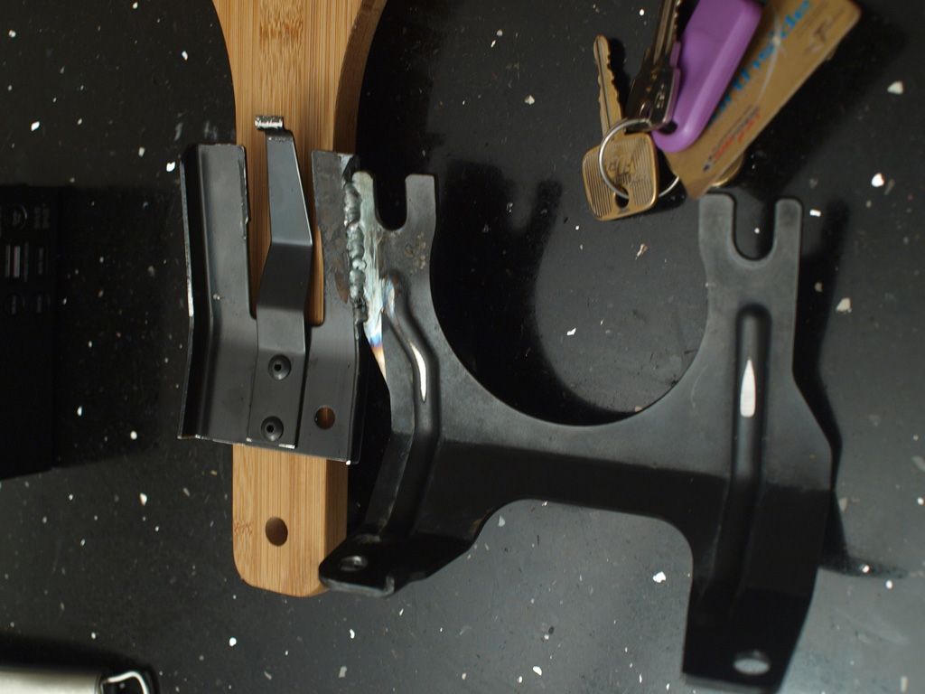
Got to Dapto pick-a-part this morning and got myself a gearbox crossmember with a bit more clearance
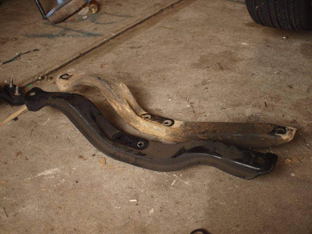
Seems like pretty much anything gen 2 or newer have that extra clearance on the LH side, and they have redesigned the cross member a couple of times. Some are more boxed in and stronger than others (this appears to be the older models and turbos), and some have a slightly different transmission mount height (old models look consistent, phase two 5 speeds, which I only was able to see in imprezas, look like the mounts lower). So I chose to take one off a gen 2 liberty as the rest of the cross member is exactly the same. I bought the whole cross member, but only changed the part shown in the photo. No other crossmembers have extra space around the tail shaft end which is unfortunate.
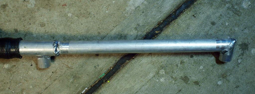
Went to an exhaust shop and picked up a bend, a flange and some gaskets to get the exhaust underway.
My good friend and housemate, who works part time at a motorsports engineering shop specializing in exhaust manifolds, helped me cut and shut the exhaust. Started by removing the heatsheild, mounting the manifold on the car and making some marks.
Then went to the welder, tacked the header flanges flat to the welding table and removed the offending section of pipe.
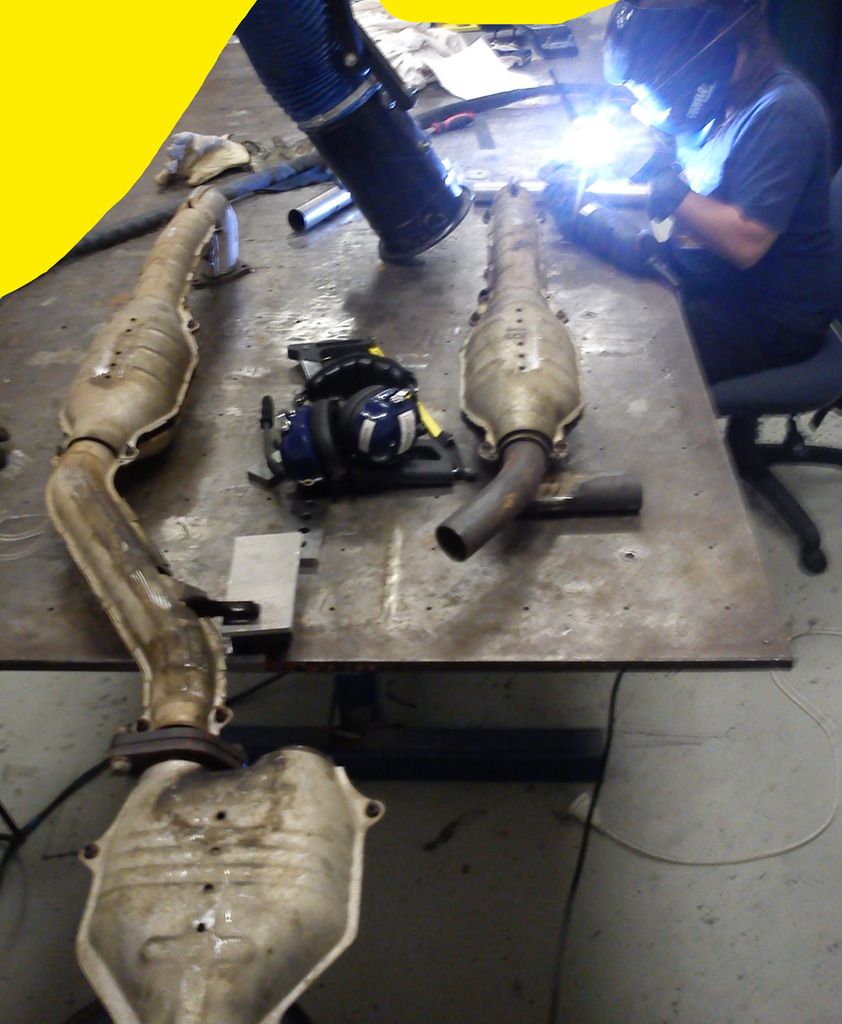
After building up and welding in the modified section, ground the tacks off and she's done.
My friend is a genius. They fit great, and the welds pulled less than 5mm at the header flanges.
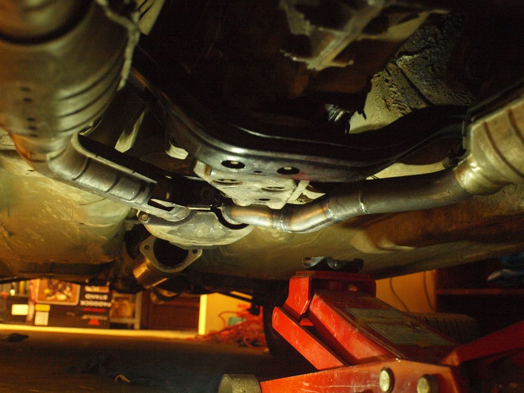
Once placed on the hanger, there was a small interference on the LH side where the heat shield still contacted the cross member. Solution to that was to jack the exhaust up onto the cross member crush the heat sheild down. Now there is about 5mm clearnace, so it will probably hit a little. If the contact is annoying, regular or bad I will fix it. But we'll see how it goes.
Oh, and the intake from the H6 bolts up almost exactly where the old airbox used to go. So no custom solutions required there. Zero. Zip. Not even some flexible hose. Who would have thought that.
So headers are done. Only thing left to do with the exhaust is the make a small joiner section to mate onto the rest of the system
Got to Dapto pick-a-part this morning and got myself a gearbox crossmember with a bit more clearance
Seems like pretty much anything gen 2 or newer have that extra clearance on the LH side, and they have redesigned the cross member a couple of times. Some are more boxed in and stronger than others (this appears to be the older models and turbos), and some have a slightly different transmission mount height (old models look consistent, phase two 5 speeds, which I only was able to see in imprezas, look like the mounts lower). So I chose to take one off a gen 2 liberty as the rest of the cross member is exactly the same. I bought the whole cross member, but only changed the part shown in the photo. No other crossmembers have extra space around the tail shaft end which is unfortunate.
Went to an exhaust shop and picked up a bend, a flange and some gaskets to get the exhaust underway.
My good friend and housemate, who works part time at a motorsports engineering shop specializing in exhaust manifolds, helped me cut and shut the exhaust. Started by removing the heatsheild, mounting the manifold on the car and making some marks.
Then went to the welder, tacked the header flanges flat to the welding table and removed the offending section of pipe.
After building up and welding in the modified section, ground the tacks off and she's done.
My friend is a genius. They fit great, and the welds pulled less than 5mm at the header flanges.
Once placed on the hanger, there was a small interference on the LH side where the heat shield still contacted the cross member. Solution to that was to jack the exhaust up onto the cross member crush the heat sheild down. Now there is about 5mm clearnace, so it will probably hit a little. If the contact is annoying, regular or bad I will fix it. But we'll see how it goes.
Oh, and the intake from the H6 bolts up almost exactly where the old airbox used to go. So no custom solutions required there. Zero. Zip. Not even some flexible hose. Who would have thought that.
So headers are done. Only thing left to do with the exhaust is the make a small joiner section to mate onto the rest of the system
-
El_Freddo
- Master Member
- Posts: 12704
- Joined: Tue Oct 04, 2005 10:00 am
- Location: Bridgewater Vic
- Contact:
That's the one (above post of Venom's H6).
Neat work on the exhaust!
The air box fitment does t surprise me - Subaru essentially have not changed the engine bay layout in a very long time! Lego!
How long until you reckon you'll be driving this? And I bet it sounds a bit better with the extractors on it to the mid section!
Cheers
Bennie
Neat work on the exhaust!
The air box fitment does t surprise me - Subaru essentially have not changed the engine bay layout in a very long time! Lego!
How long until you reckon you'll be driving this? And I bet it sounds a bit better with the extractors on it to the mid section!
Cheers
Bennie

-
Donkeytits1
- Junior Member
- Posts: 97
- Joined: Tue Feb 07, 2012 12:20 pm
- Location: Canberra
Haha! Yeah the shifters gone - or as we know it - the Swedish Nut Lathe
I'm gonna keep using the battery that was in the 1st gen car. It was originally speced with a puny 40 Amp hour thing. I enlarged it to 60 amp hour around a year ago. That's the biggest battery that will sit in the battery cradle. The H6 looks like it has an 80 Amp hour, but the little battery has more than enough power to crank it. And conveniently, the H6 battery fits in another car we own. So ace.
Benny: Yeah 'Lego', holy sh!t, I don't believe it. Its making it too easy! It won't look modded enough bro, I'll get no cred! :P
Should be driving tonight once I stick my hacked up rad system in. Exhaust will be ending at the headers, so won't have to tell the neighbours, they'll know whats happening.
If you are in Canberra esp Northside with Summernats on can I suggest don't unless you're 100% sure it's absolutely, perfectly legit on road? I think the cops are just looking for excuses...Donkeytits1 wrote: Should be driving tonight once I stick my hacked up rad system in. Exhaust will be ending at the headers, so won't have to tell the neighbours, they'll know whats happening.
...It won't look modded enough bro, I'll get no cred! :P
...But the 'no mods' look just might save you
Good stuff. Just replaced a battery in our 2.2l Mazda diesel, the NRMA took it from ~60Ah to 90Ah. Should run South Aust. for 20 mins or so in an emergencyDonkeytits1 wrote:Haha! Yeah the shifters gone - or as we know it - the Swedish Nut Lathe
I'm gonna keep using the battery that was in the 1st gen car. It was originally speced with a puny 40 Amp hour thing. I enlarged it to 60 amp hour around a year ago. That's the biggest battery that will sit in the battery cradle. The H6 looks like it has an 80 Amp hour, but the little battery has more than enough power to crank it. And conveniently, the H6 battery fits in another car we own. So ace.
No not too easy, just the result of good research and prep. Well done!Donkeytits1 wrote:Benny: Yeah 'Lego', holy sh!t, I don't believe it. Its making it too easy!
Patrick
Ex- 2010 Forester Diesel
Ex- 2010 Forester Diesel