Silverbullets' resto: Interior

-
Green_eyed_liberty

- Junior Member
- Posts: 374
- Joined: Wed Oct 05, 2005 10:00 am
- Location: Gold Coast
what i did with my sports cluster is sit down with pencil and paper back trace each number,
(most of the wires are in the factory brumby loom, same colours and all, mostly needed to add illumination as its required a few times in the sports cluster)
* pin 1, illumination red/green
* pin 2, illumination red
* pin 3, park brake light blue
etc etc, you follow each pin circuit to its destination (remove the bulb and shine a light to see)
the clock was just illumination, earth and constant power
-
Silverbullet

- Senior Member
- Posts: 2953
- Joined: Mon Aug 23, 2010 6:20 pm
- Location: Adelaide
Not all doom and gloom ehGreen_eyed_liberty wrote:what i did with my sports cluster is sit down with pencil and paper back trace each number,
(most of the wires are in the factory brumby loom, same colours and all, mostly needed to add illumination as its required a few times in the sports cluster)
* pin 1, illumination red/green
* pin 2, illumination red
* pin 3, park brake light blue
etc etc, you follow each pin circuit to its destination (remove the bulb and shine a light to see)
the clock was just illumination, earth and constant power
Will it ever end!?
-EA81 TWIN CARB!!!!
-L series 5 speed
-Custom paint job
-2" lift
-Full custom re-wire
-L series front end
-EA81 TWIN CARB!!!!
-L series 5 speed
-Custom paint job
-2" lift
-Full custom re-wire
-L series front end

-
Silverbullet
- Senior Member
- Posts: 2953
- Joined: Mon Aug 23, 2010 6:20 pm
- Location: Adelaide
Just finished the updated schematic for my 6 gauge instrument cluster. And yes, it was completely different to the FSM and the FSM even had a few typos which added to my confusion. So I've drawn up a new clean copy and added it to the downloads section as .pdf in case anyone wanted to have a look/make use of it.
downloads.php?do=file&id=148
downloads.php?do=file&id=148
Will it ever end!?
-EA81 TWIN CARB!!!!
-L series 5 speed
-Custom paint job
-2" lift
-Full custom re-wire
-L series front end
-EA81 TWIN CARB!!!!
-L series 5 speed
-Custom paint job
-2" lift
-Full custom re-wire
-L series front end
-
Silverbullet
- Senior Member
- Posts: 2953
- Joined: Mon Aug 23, 2010 6:20 pm
- Location: Adelaide
Intermittent wipers w/relays
Just working out and adding the last circuits to my diagram, one of them being the wipers, 2 speed with self park AND intermittent. Since I'm re-wiring from scratch I'm not going to use the stock intermittent relay, since I have NFI what the 6 pins on it do and they are not labelled. Intermittent timer circuits are easy to come by if not build one myself to send out a pulse of power for say half a second every 5 seconds. So this is what I've come up with, can anyone see any problems? (DOUG! need your seal of approval!  )
)
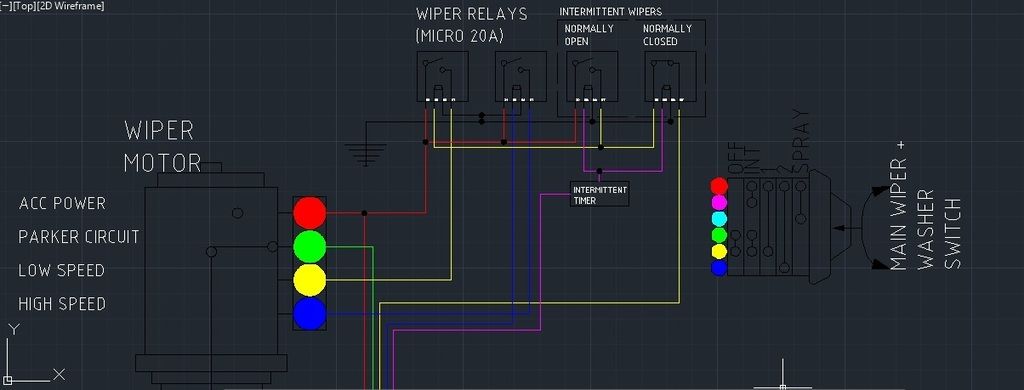
Hope the lines are visible enough. I've put the wiper switch right next to the motor just for that image to show what wires do what in relation to switch positions. Red on the switch and motor are ACC power (separate feeds of course) with all the outputs from the switch going to signal the relays which will actually deliver the power to the motor. When the motor has turned past a certain point the self-park cam comes into action and delivers power from the red to the green on the motor, which then goes back to the switch. When the switch is in the OFF position (or INT for that matter) the green is joined to the yellow, sending power to the low speed winding in the motor UNTIL the wipers get to the home position, self park cam cuts power to the green therefore cutting power to the low speed winding, stopping the motor in home position...clear as mud?
The tricky bit is the intermittent switch position. You'll see I have the signal for the "low speed" relay going through a normally closed relay, so in any switch position other than INT the signal for the low speed relay will be un-interrupted. With the switch in the INT position however, power is sent to the timer circuit, which pulses a signal every 5 seconds to signal 2 relays. When this happens, the normally open relay closes sending power to the low speed winding (wiping the window once every 5 seconds) at the same time the normally closed relay opens cutting the signal to the "low speed" relay. This is so that the low speed winding only gets power from one relay at a time (which it should anyway, the normally closed relay is sort of a safety) Since the pulse will only be .5 seconds, the aforementioned self-park cam should still park the wipers at home position because the green and yellow are still joined with the switch in the INT position.
I think this should work, but I'm not sure if there would be point when the .5 second pulse stops that the wipers would stop for a split second in the middle of the window (DOUG! )
)
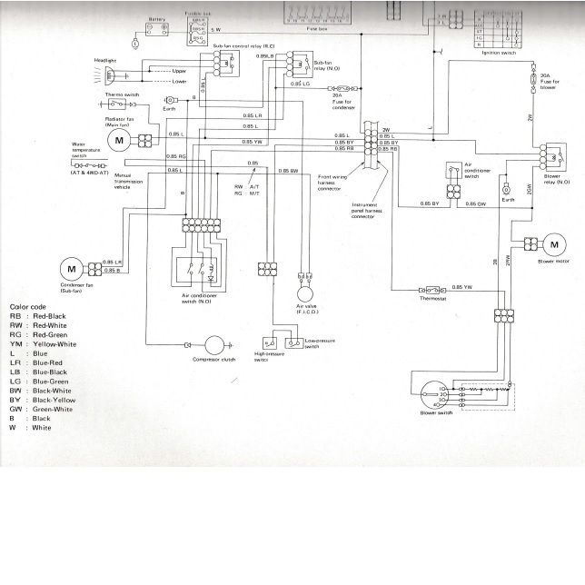
If anyone kept track of all that my hat is off to you") And while I'm here, does anyone know what the "Air conditioner switch N.O" component in the FSM diagram below refers to? If you can see it, middle-left of the page with 6 wires going to it. This can't be the A/C switch in the dash, since that only has 4 wires. Is there another switch somewhere in an MY A/C system? The A/C is pretty much the last circuit I have to draw in, probably the most complicated too.
And while I'm here, does anyone know what the "Air conditioner switch N.O" component in the FSM diagram below refers to? If you can see it, middle-left of the page with 6 wires going to it. This can't be the A/C switch in the dash, since that only has 4 wires. Is there another switch somewhere in an MY A/C system? The A/C is pretty much the last circuit I have to draw in, probably the most complicated too.
Hope the lines are visible enough. I've put the wiper switch right next to the motor just for that image to show what wires do what in relation to switch positions. Red on the switch and motor are ACC power (separate feeds of course) with all the outputs from the switch going to signal the relays which will actually deliver the power to the motor. When the motor has turned past a certain point the self-park cam comes into action and delivers power from the red to the green on the motor, which then goes back to the switch. When the switch is in the OFF position (or INT for that matter) the green is joined to the yellow, sending power to the low speed winding in the motor UNTIL the wipers get to the home position, self park cam cuts power to the green therefore cutting power to the low speed winding, stopping the motor in home position...clear as mud?
The tricky bit is the intermittent switch position. You'll see I have the signal for the "low speed" relay going through a normally closed relay, so in any switch position other than INT the signal for the low speed relay will be un-interrupted. With the switch in the INT position however, power is sent to the timer circuit, which pulses a signal every 5 seconds to signal 2 relays. When this happens, the normally open relay closes sending power to the low speed winding (wiping the window once every 5 seconds) at the same time the normally closed relay opens cutting the signal to the "low speed" relay. This is so that the low speed winding only gets power from one relay at a time (which it should anyway, the normally closed relay is sort of a safety) Since the pulse will only be .5 seconds, the aforementioned self-park cam should still park the wipers at home position because the green and yellow are still joined with the switch in the INT position.
I think this should work, but I'm not sure if there would be point when the .5 second pulse stops that the wipers would stop for a split second in the middle of the window (DOUG!
If anyone kept track of all that my hat is off to you
Will it ever end!?
-EA81 TWIN CARB!!!!
-L series 5 speed
-Custom paint job
-2" lift
-Full custom re-wire
-L series front end
-EA81 TWIN CARB!!!!
-L series 5 speed
-Custom paint job
-2" lift
-Full custom re-wire
-L series front end
-
Bantum

- Senior Member
- Posts: 2052
- Joined: Sun Jul 29, 2012 4:30 pm
- Location: Northern Territory + QLD
- Contact:
Kewl Running ...
Damn your good, I think you have got the hang of it quite nicely - I'm going to do the same for the Brumby ( might borrow some of what you have done ) ...
Yep the peg board works a treat, although you might want to be able to lay it flat at times as it will get heavy as you lay out more wires ...
For the intermittent wiper - I'd just use the original relay ( if you still have it ) & wire it as per the manual.
The A/C system has three relays from memory - ( all located just above the coil on strut tower ) N.O. stands for 'normally open' relay - so when A/C switch is turned on in the cabin it turns on the system - triggered via those relays which also controls the cooling fans, condenser, etc. There's only two manual A/C switches : the On / Off switch , and the blower fan switch - both are in the center consul.
Keep at it ...
Cheers, Bantum ...
-
Silverbullet
- Senior Member
- Posts: 2953
- Joined: Mon Aug 23, 2010 6:20 pm
- Location: Adelaide
Cheers Bantum  Feel free to use anything you like. I plan to post up my whole car wiring diagram when it's done for anyone to use, if they are feeling adventurous
  I do have an original Mitsuba intermittent wiper relay for an MY, but it is wired up very strangely in the book, the washer bottle motor is connected to it too, maybe for wash+wipe function? I wasn't planning on using it just because it's not really compatible with my planned wipers system. My Brum doesn't have wash+wipe and the wagon never did either so I think I can live without it
I was aware of the 3 relays on the strut tower, I have them in my possession. There is also one other relay under the dash (blower relay on the above diagram) I just can't work out what the "Air conditioner switch" is in that diagram. Seems to have 2 internal contacts, a resistor and a diode inside. I can't work out if it is another relay or an actual switch. The resistor+diode combo is connected to the blower fan switch via thermostat and a dead end near the high and low pressure switches.
I was aware of the 3 relays on the strut tower, I have them in my possession. There is also one other relay under the dash (blower relay on the above diagram) I just can't work out what the "Air conditioner switch" is in that diagram. Seems to have 2 internal contacts, a resistor and a diode inside. I can't work out if it is another relay or an actual switch. The resistor+diode combo is connected to the blower fan switch via thermostat and a dead end near the high and low pressure switches.
Will it ever end!?
-EA81 TWIN CARB!!!!
-L series 5 speed
-Custom paint job
-2" lift
-Full custom re-wire
-L series front end
-EA81 TWIN CARB!!!!
-L series 5 speed
-Custom paint job
-2" lift
-Full custom re-wire
-L series front end
-
Proton mouse
- Junior Member
- Posts: 378
- Joined: Mon Nov 06, 2006 11:35 pm
- Location: Diagonally parked in a parallel universe
Having worked on and parted out several A/C systems I can say there is no other 'switch' you are looking for SB.
As far as I can make out by your pic (it comes up a bit pixelated when blown up) they are referring to the main one, of those 3 strut tower relays.
Some systems I've seen have 4 relays btw.
As far as I can make out by your pic (it comes up a bit pixelated when blown up) they are referring to the main one, of those 3 strut tower relays.
Some systems I've seen have 4 relays btw.
-
Silverbullet
- Senior Member
- Posts: 2953
- Joined: Mon Aug 23, 2010 6:20 pm
- Location: Adelaide
I think you're right Proton, dug out the A/C kit you sold me There is a relay with 6 pins, this must be the "A/C switch" in that diagram.
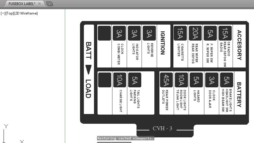
Today was more fiddling and fettling finishing off my wiring diagram before I go and try and get it printed out + laminated. Also got the fuse box from the NZ dash loom I have (now surplus to requirements) and hacked the fuse box off, removed all the fuse terminals to give me a blank canvas to work with as it were You can buy these crimp on fuse terminals that clip in perfectly to the stock fuse box so I plan to start fresh and re-purpose it for my own needs. Also steamed off the aging sticker from inside the lid, scanned it into PC and made my own version for that completely custom feel a few empty slots yet, will probably get used up.
Interesting to see how they bussed all the ACC, IGN and BATT circuits together originally! Just imagine all these thick wires getting their power through that 30 year old ignition switch! *shudder*
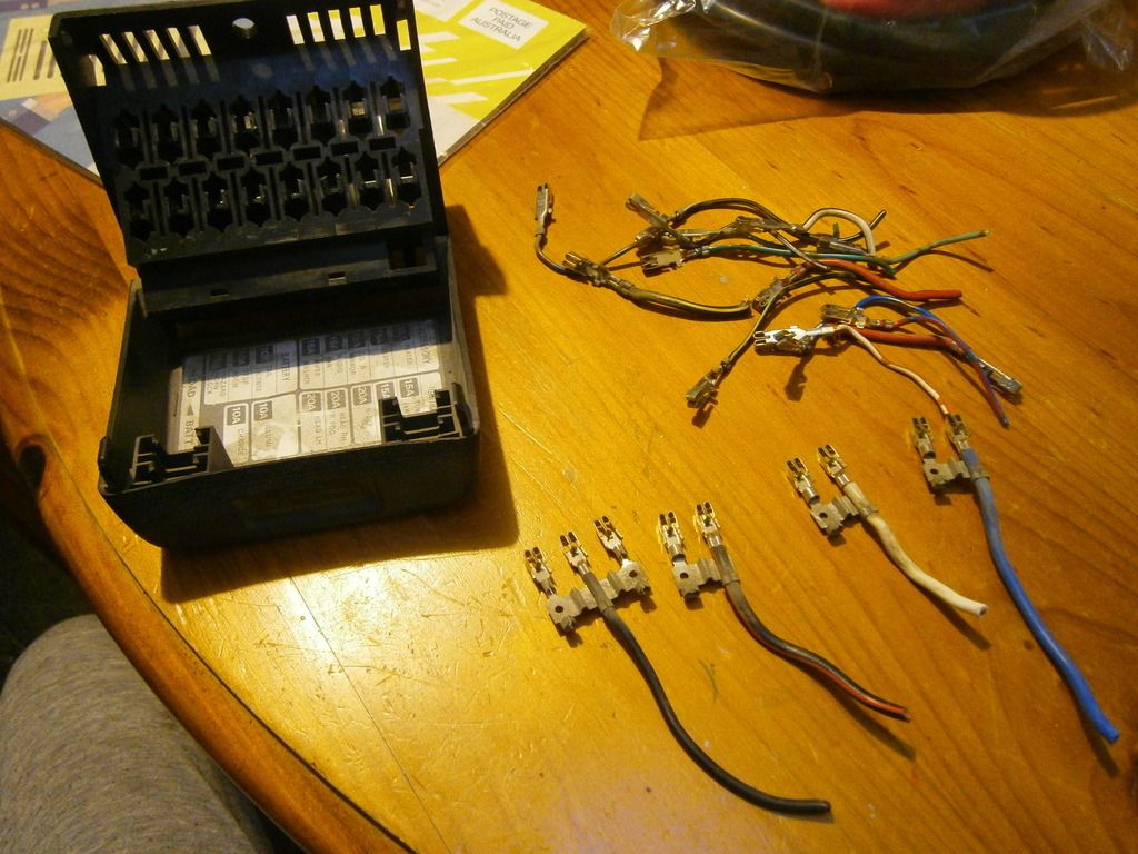
New fuse box label! Notice almost everything will have substantially lower rated fuses than before, because it's all driving relay coils and LEDs!
Today was more fiddling and fettling finishing off my wiring diagram before I go and try and get it printed out + laminated. Also got the fuse box from the NZ dash loom I have (now surplus to requirements) and hacked the fuse box off, removed all the fuse terminals to give me a blank canvas to work with as it were
Interesting to see how they bussed all the ACC, IGN and BATT circuits together originally! Just imagine all these thick wires getting their power through that 30 year old ignition switch! *shudder*
New fuse box label! Notice almost everything will have substantially lower rated fuses than before, because it's all driving relay coils and LEDs!
Will it ever end!?
-EA81 TWIN CARB!!!!
-L series 5 speed
-Custom paint job
-2" lift
-Full custom re-wire
-L series front end
-EA81 TWIN CARB!!!!
-L series 5 speed
-Custom paint job
-2" lift
-Full custom re-wire
-L series front end
-
steptoe
- Master Member
- Posts: 11582
- Joined: Thu Oct 06, 2005 10:00 am
- Location: 14 miles outside Gotham City
on the Mitsuba - gosh, that mariage was close wasn't it ? I recently saw MY wagons with intermittent wipers and the knob was a two tiered set up, unlike my Brumby sourced single tiered switch. Second tier just the rear wiper squirter ? Guess same can controller ? Wonder if your wire diagram reflects the two switches in MY and MV ?
-
Silverbullet
- Senior Member
- Posts: 2953
- Joined: Mon Aug 23, 2010 6:20 pm
- Location: Adelaide
Jonno, you're right there is a 2 tiered switch setup in the wagons, for the rear wiper + washer as well. There's 2 rotary can style switches bolted together inside the dash, with a shaft passing straight through the first one to the switch behind. Each switch has its own plug I think, rear wiper one having only 3 or 4 wires as opposed to front with 5.
Anywhoo...I love it when goodies arrive Takes my mind of being bored not at work and with a nasty cold
This lot cost a pretty penny I can assure you!
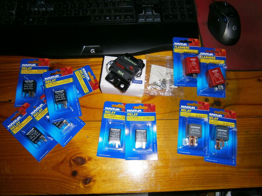
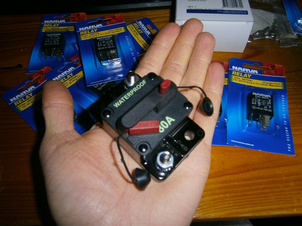
And with two of these bad boys I hope to never see a fusible link in my life again! Can be manually operated too to isolate that whole side of the wiring if need be, and that red tab pops out when it is tripped as a visual aid when you're looking around under the bonnet.
As we speak my wiring diagram is getting blown up and printed + laminated in A0 size, picking that up later today.
Anywhoo...I love it when goodies arrive
This lot cost a pretty penny I can assure you!
And with two of these bad boys I hope to never see a fusible link in my life again!
As we speak my wiring diagram is getting blown up and printed + laminated in A0 size, picking that up later today.
Will it ever end!?
-EA81 TWIN CARB!!!!
-L series 5 speed
-Custom paint job
-2" lift
-Full custom re-wire
-L series front end
-EA81 TWIN CARB!!!!
-L series 5 speed
-Custom paint job
-2" lift
-Full custom re-wire
-L series front end
-
Silverbullet
- Senior Member
- Posts: 2953
- Joined: Mon Aug 23, 2010 6:20 pm
- Location: Adelaide
A wiring loom is born!

A few points worth mentioning:
- I VASTLY under-estimated the amount of wire I was going to need! And the number of different colors, and gauge. I've already doubled up on some colors and run out of others, can't do the wiring for the front fog lights as I don't have a gauge thick enough apart from the 6mm which is too thick Also going to need about every different color/stripe combination for all the relays, sensors and dash lights.
- Not sure if the peg board is really worth the effort. It's a bit fiddly as in you can't "hang" the wires up there, they're too stiff/springy and have a mind of their own, had to tape, zip tie and clip them all together and onto the rope. But for getting the length and position right it's pretty good, not having to thread each wire one by one through the firewall and engine bay.
- I need plain/un-insulated wire splices (picture brass tube) The heat shrink insulated ones are okay but you have to physically cut the wire and then re-join using the splice instead of stripping one wire in the middle of its length and just adding the other one. Having 2 wires in one side that don't want to fit in and one wire the other side which is almost too small for the heat shrink.
I'm thinking about finishing up the longest wires in the engine bay (fog lights) and just doing the rest in the car, being all the wires between the inside fuse box and light switches, relays etc. Since those will only be 30-50cm long at most there's not much point doing them on the board.
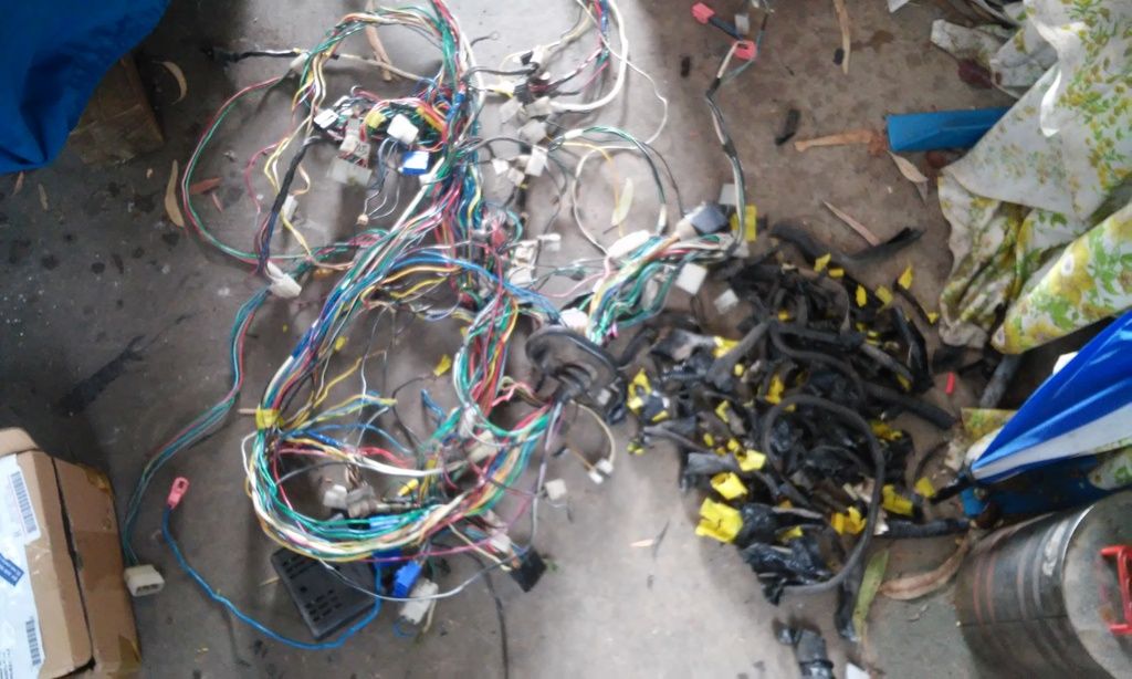
Also the other day I peeled the old loom of its tape and covering, salvaged what wires I could but interestingly none of them are very long before they meet a splice or connector, so not much usable came from it. And man, was this an eye-opening experience! The whole lot is so simple and almost pre-historic Glad I'm upgrading it.
A few points worth mentioning:
- I VASTLY under-estimated the amount of wire I was going to need!
- Not sure if the peg board is really worth the effort. It's a bit fiddly as in you can't "hang" the wires up there, they're too stiff/springy and have a mind of their own, had to tape, zip tie and clip them all together and onto the rope. But for getting the length and position right it's pretty good, not having to thread each wire one by one through the firewall and engine bay.
- I need plain/un-insulated wire splices (picture brass tube) The heat shrink insulated ones are okay but you have to physically cut the wire and then re-join using the splice instead of stripping one wire in the middle of its length and just adding the other one. Having 2 wires in one side that don't want to fit in and one wire the other side which is almost too small for the heat shrink.
I'm thinking about finishing up the longest wires in the engine bay (fog lights) and just doing the rest in the car, being all the wires between the inside fuse box and light switches, relays etc. Since those will only be 30-50cm long at most there's not much point doing them on the board.
Also the other day I peeled the old loom of its tape and covering, salvaged what wires I could but interestingly none of them are very long before they meet a splice or connector, so not much usable came from it. And man, was this an eye-opening experience! The whole lot is so simple and almost pre-historic
Will it ever end!?
-EA81 TWIN CARB!!!!
-L series 5 speed
-Custom paint job
-2" lift
-Full custom re-wire
-L series front end
-EA81 TWIN CARB!!!!
-L series 5 speed
-Custom paint job
-2" lift
-Full custom re-wire
-L series front end
-
Silverbullet
- Senior Member
- Posts: 2953
- Joined: Mon Aug 23, 2010 6:20 pm
- Location: Adelaide
What a day I'v got so much done in the last 2 days it feels like I'm making heaps of progress.
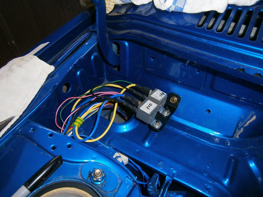
I did about all I could on the board (not as much as I thought as it turned out...was hardly worth putting all the effort into the peg board!) Tidied up the wires with strategically placed bands of electrical tape and grouped the breakout points and then transferred the whole lot into the car/engine bay. The loom-to-be measured up absolutely (I mean perfectly) with all the wires exactly the right length and the breakouts in exactly the right place. Created some bracketry to mount the Lib fuse box and went about crimping and installing all the new wires into the Lib plugs for a plug and play affair. Hardest bit was removing the old terminals from the plugs; a flattened and perfectly shaped nail was the only thing small enough to get in there to lift the locking tab. Then today was more crimping, heat shrinking, plugging in, mounted and wired up 3x relays near the battery for high beams, "ON" power (fuel pump, ignition coil, fuel cutoff solenoid) and "START" power (starter motor solenoid) I got relays with 2 x output pins on them sort of by accident but it turned out to be really useful for powering multiple items from 1 relay.
So now the Lib fuse box is installed and 90% wired up. Just need a couple extra wires for the thermo fan relays. I used my test power probe in combo with the multimeter to test all the relays and to see if all the (imaginary at the moment) accessories were getting power from the fuse box, 100% all working perfectly Tomorrow I have to mount 2 x 50A heavy duty relays up near the firewall that will throw power into the interior fuse box, then I can start wiring up the internal fuse box and internal accessories. The 50A relays have big copper spade terminals on them (must be 10mm?) would you believe the "10mm" crimp terminals I ordered aren't big enough! Must be 9.80mm and the buggers just don't go on. Maybe I'll try and get some relay holders for these. One other interesting thing; I went to re-use some wires from the original loom, cut the ends back a bit and stripped them...the copper strands were all dark green! Cut back some more; still green! Almost every wire I tried was pretty much green or patchy all the way through. Glad I'm replacing this!
Just thinking...I could almost make a plug and play kit for people to upgrade their MY's to Lib fuse box and relay power, being that I'm pretty well un-employed at the moment
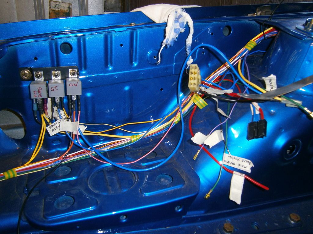
Baby wiring loom in the engine bay
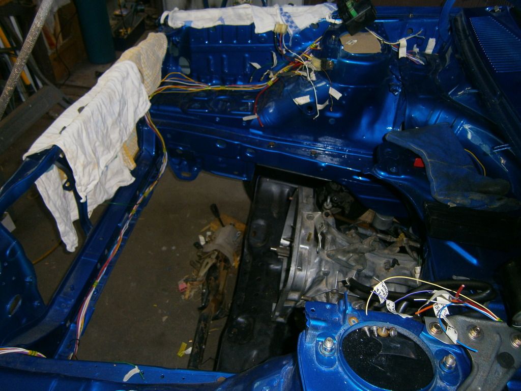
It's a bit of tangle near the fuse box at the moment, but here are the plugs all wired up. I'll sort this out better when it comes to wrapping the loom
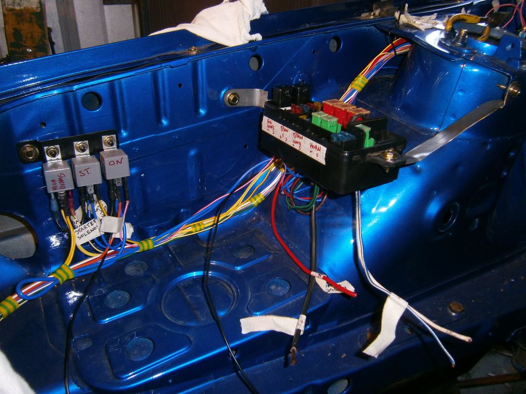
Relays and fuse box installed; The dodgy looking bracket holding the fuse box to the strut tower will be replaced with something stronger and prettier, but it does the job for now.
Looking good!
I did about all I could on the board (not as much as I thought as it turned out...was hardly worth putting all the effort into the peg board!) Tidied up the wires with strategically placed bands of electrical tape and grouped the breakout points and then transferred the whole lot into the car/engine bay. The loom-to-be measured up absolutely (I mean perfectly) with all the wires exactly the right length and the breakouts in exactly the right place. Created some bracketry to mount the Lib fuse box and went about crimping and installing all the new wires into the Lib plugs for a plug and play affair. Hardest bit was removing the old terminals from the plugs; a flattened and perfectly shaped nail was the only thing small enough to get in there to lift the locking tab. Then today was more crimping, heat shrinking, plugging in, mounted and wired up 3x relays near the battery for high beams, "ON" power (fuel pump, ignition coil, fuel cutoff solenoid) and "START" power (starter motor solenoid) I got relays with 2 x output pins on them sort of by accident but it turned out to be really useful for powering multiple items from 1 relay.
So now the Lib fuse box is installed and 90% wired up. Just need a couple extra wires for the thermo fan relays. I used my test power probe in combo with the multimeter to test all the relays and to see if all the (imaginary at the moment) accessories were getting power from the fuse box, 100% all working perfectly
Just thinking...I could almost make a plug and play kit for people to upgrade their MY's to Lib fuse box and relay power, being that I'm pretty well un-employed at the moment
Baby wiring loom in the engine bay
It's a bit of tangle near the fuse box at the moment, but here are the plugs all wired up. I'll sort this out better when it comes to wrapping the loom
Relays and fuse box installed; The dodgy looking bracket holding the fuse box to the strut tower will be replaced with something stronger and prettier, but it does the job for now.
Looking good!
Will it ever end!?
-EA81 TWIN CARB!!!!
-L series 5 speed
-Custom paint job
-2" lift
-Full custom re-wire
-L series front end
-EA81 TWIN CARB!!!!
-L series 5 speed
-Custom paint job
-2" lift
-Full custom re-wire
-L series front end
-
Green_eyed_liberty
- Junior Member
- Posts: 374
- Joined: Wed Oct 05, 2005 10:00 am
- Location: Gold Coast
I'm liking this revelation. i will defiantly employ your services for my BrumbySilverbullet wrote:
Just thinking...I could almost make a plug and play kit for people to upgrade their MY's to Lib fuse box and relay power, being that I'm pretty well un-employed at the moment
(quad headlight, sports dash, aircon
-
Bantum
- Senior Member
- Posts: 2052
- Joined: Sun Jul 29, 2012 4:30 pm
- Location: Northern Territory + QLD
- Contact:
Kewl - like it ...
What are you doing for ignition ? - upgrade to Electronic ?
I would also try & run the wires hidden as much as possible - like over top of radiator behind / inside fenders, etc. to help keep it clean & tidy ...
You should checkout the 'Drag Brumby' for inspiration : https://www.facebook.com/Drag-Brumby-89 ... /timeline/
Cheers, Bantum ...
-
Silverbullet
- Senior Member
- Posts: 2953
- Joined: Mon Aug 23, 2010 6:20 pm
- Location: Adelaide
Heh that drag Brumby is tidy all right, not a wire in sight! I didn't plan on hiding everything so it's probably too late now to run the loom through the fenders, since all the wires would be too short. Not too fussed about hiding them though, once it's all wrapped up it will look neat enough for me anyway.
As for ignition, I'm probably going to do an EDIS programmable setup (megajolt or some such) and do away with the original coil and dizzy...and not only because I put the new fuse box where the coil should be but I've always hated the original ignition systems points or electronic. They've always been a huge failing point and have left me stranded and frustrated more than once. I'm going all out on everything else with this car so why not ignition as well
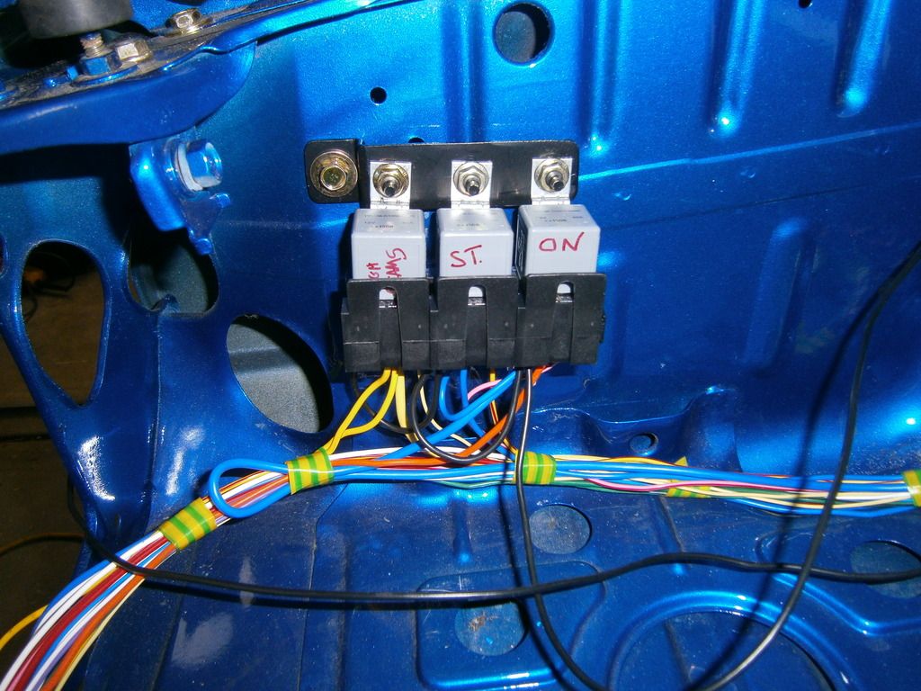
Todays progress: More relays! 2 x 50A heavy duty ones up near the firewall for the interior fuse box. Making the bracket for them took alot longer than planned since my angle grinder has decided it doesn't want to be parted from its beloved wire brush...had to cut everything with hacksaw and hand file
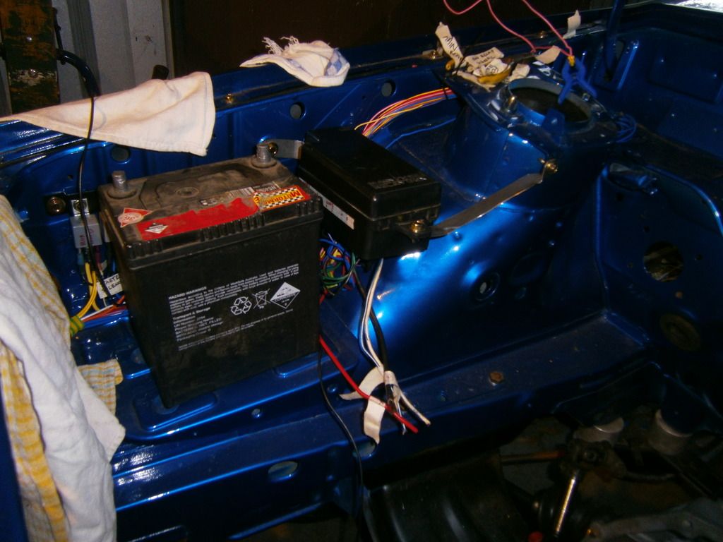
Also got some relay sockets for the 3 by the battery, looks much neater now.
New heavy duty relays mounted and wired up
New sockets for the ones I did the other day
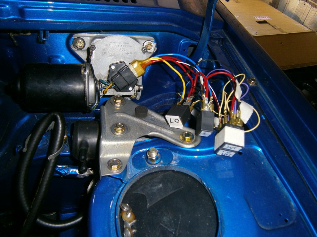
Plus my intermittent wipers They're wired up according to the plan I made but whether they work or not is yet to be seen. I still need to wire up the switch in the cabin and sort out an intermittent pulsing circuit. I'll order some relay sockets for these to neaten it up and put them all in a sealed box near the wiper motor/fuel pump.
Plus I wired up the ignition switch and used the test power probe and checked that all my relays were working correctly...couldn't help but make a little demo vid
https://www.youtube.com/watch?v=5df3zQg ... e=youtu.be
As for ignition, I'm probably going to do an EDIS programmable setup (megajolt or some such) and do away with the original coil and dizzy...and not only because I put the new fuse box where the coil should be but I've always hated the original ignition systems points or electronic. They've always been a huge failing point and have left me stranded and frustrated more than once. I'm going all out on everything else with this car so why not ignition as well
Todays progress: More relays! 2 x 50A heavy duty ones up near the firewall for the interior fuse box. Making the bracket for them took alot longer than planned since my angle grinder has decided it doesn't want to be parted from its beloved wire brush...had to cut everything with hacksaw and hand file
Also got some relay sockets for the 3 by the battery, looks much neater now.
New heavy duty relays mounted and wired up
New sockets for the ones I did the other day
Plus my intermittent wipers
Plus I wired up the ignition switch and used the test power probe and checked that all my relays were working correctly...couldn't help but make a little demo vid
https://www.youtube.com/watch?v=5df3zQg ... e=youtu.be
Will it ever end!?
-EA81 TWIN CARB!!!!
-L series 5 speed
-Custom paint job
-2" lift
-Full custom re-wire
-L series front end
-EA81 TWIN CARB!!!!
-L series 5 speed
-Custom paint job
-2" lift
-Full custom re-wire
-L series front end

-
Silverbullet
- Senior Member
- Posts: 2953
- Joined: Mon Aug 23, 2010 6:20 pm
- Location: Adelaide
I know right!El_Freddo wrote:Top effort mate!
I too was going to sugget hiding the wiring but if you're happy with it that's all that matters!
I still can't get over the paint job on that wagon!!
Cheers
Bennie
More progress today on the wiring; it feels like I'm flying through it and I'm testing every circuit as I go and so far everything has worked flawlessly. Seriously that test power probe is the single best $50 I've spent so far on this wiring overhaul. Followed by the wire stripper and ratcheting crimp tool with changeable jaws.
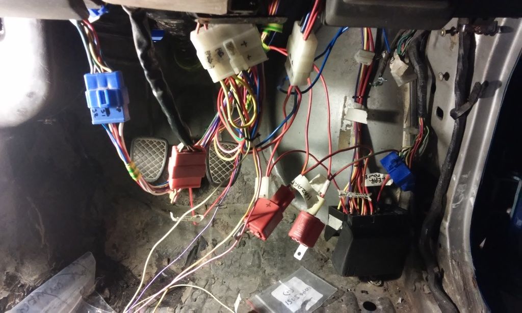
Last couple of days has been spent under the dash. I've bussed all the ACC, ON and BATT fuses together on the interior fuse box, now just adding the other side of each fuse one by one as I complete the circuits in the car. I've put a dedicated lead from the battery to the interior fuse box for the rear power sockets I have planned so no splices or cuts in it for reliability. I've also completed the headlights switch, high beam and indicator/hazard switch (plug with 10 wires in it!) complete with new LED flasher cans and front wiper/washer switch with intermittent function. I managed to rig everything up with the power probe to test my 4 relay wiper arrangement and it works perfectly, self parking feature and all
Have to say this wiring job is coming together really well and I am actually enjoying it, not as daunting as I first thought and the end result is going to be so much better than original. Now I pretty much have to start doing the rear end of the car, for this the main lead back there will be 7 core trailer cable, with a few extra wires following it down for any extras.
All the plugs correctly wired and working. Everything is just mocked up at the moment to get wire lengths right, it will all come out again so I can clean the floor up and put sound deadening down.
Will it ever end!?
-EA81 TWIN CARB!!!!
-L series 5 speed
-Custom paint job
-2" lift
-Full custom re-wire
-L series front end
-EA81 TWIN CARB!!!!
-L series 5 speed
-Custom paint job
-2" lift
-Full custom re-wire
-L series front end
-
El_Freddo

- Master Member
- Posts: 12709
- Joined: Tue Oct 04, 2005 10:00 am
- Location: Bridgewater Vic
- Contact:
Another thought - get a battery box! You don't want battery acid ruining your Purdy paint job!! Plus a battery box looks neat as when you've got the right box in there
I too love wiring, mine is not as neat as that as I've just added what I've needed, when needed and typically laid it over the top of everything else in there. The EJ conversion wiring is another thing though, there's only one thing I'd change in that if it ever comes out of the vehicle again
Cheers
Bennie